


I am still experimenting several Zephyr RTOS use case, focusing on tying up together electronics and application software.
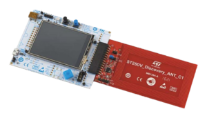
With that in mind, I took a discontinued 2016 ST25DV-DISCOVERY kit from my drawer, a kit I got from an electronics lab decluttering. It features a display and a 4-directions button kind of like a joystick, and I wanted to turn this into a mini arcade game thingy. But I didn’t want to write code, and hoped to find a Pong or Tetris to reuse.
Fortunately, my board has an STM32 flavour and all drivers already supported by Zephyr, I can focus on stitching it all together.
A few links before we start:
So let’s go!
LCD display
Error 404 : datasheet not found
Display is the project crux, even more because I don’t know LCD displays very well, and it looks like a complex world where datasheets are hard to find if you don’t get them from resellers or manufacturers.
They are generally sold as modules, with integrated controllers allowing to access them with serial buses like SPI or I2C, or parallels like MIPI DSI. Most references have compatible drivers, probably because they are using the same type of controllers, but I could not find which driver to actually call, and I don’t want to disassemble the display module. For this project, I got the clue from the eval kit original source code, and found that is is equivalent to Ilitek ILI9341.
This equivalence is available to the general public and documented in Adafruit / Sparkfun catalogues.
Another discovery from display world, the new SPI LCD driver was renamed “MIPI DBI”. This standard is unknown to me, I get that it is a LCD command standard based on an SPI bus, plus 2 complementary pins: a reset and a command and data switch. It looks like it is already implemented in lots of things, but I did not see it explicitly mentioned: this a probably a long story involving tech and geopolitics, but I did not dig more into it because I have a Pong to make.
DC, WR, DCX, TE, SDA, WTF
How to fill in the device tree? The display driver needs one SPI bus, and 2 GPIOs, “reset” and “dc” (aka data / command).
        mipi_dbi {
                compatible = "zephyr,mipi-dbi-spi";
                reset-gpios = <&gpioc 1 GPIO_ACTIVE_HIGH>;
                dc-gpios = <&gpioc 0 GPIO_ACTIVE_HIGH>;
                spi-dev = <&spi2>;
                [...]
        };
boards/arm/st25dv_mb1283_disco/st25dv_mb1283_disco.dts
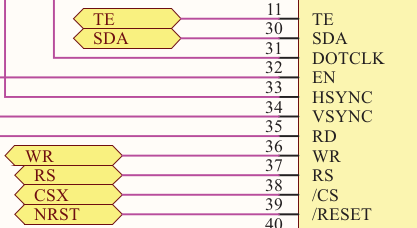
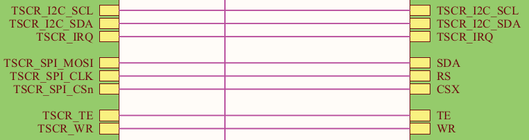
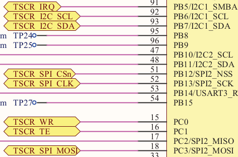
Schematics show we are using SPI but 2, except MISO is not connected. MOSI is, but it is renamed “SDA” in top level… this is no mistake, it indicates this cable can be bidirectional, because half-duplex SPI does exists, and our SDA could be named SISO or MOMI.
Bad news, my nets are called WR and TE in schematics, and don’t know who’s who. ILI9341 datasheet talks about a WRX, which looks like WR aka Write-Read, but Write-Read is only relevant for another display use case. This pin is also used as D/CX, it is the DC I was looking for, so DC is WR is GPIO PC0.
WRX (DCX)
– 8080-I /8080-II system (WRX): Serves as a write signal and writes data at the rising edge.
– 4-line system (D/CX): Serves as command or parameter select.
TE means Tearing Effect, and is used to synchronize screen writes and refreshing. It is not a reset, but I want to control this pin with the reset so it stays low while I am using the driver, hence the GPIO PC1 connect.
Driver parameters
Once the virtual MIPI DBI driver created, we add the ili9341 driver to it.
#include <zephyr/dt-bindings/display/ili9xxx.h>
[...]
        mipi_dbi {
                [...]
                write-only;

                ili9341: ili9341@0 {
                        compatible = "ilitek,ili9341";
                        mipi-max-frequency = <20000000>;
                        reg = <0>;
                        pixel-format = <ILI9XXX_PIXEL_FORMAT_RGB888>; // 1
                        rotation = <0>;
                        width = <240>;
                        height = <320>;
                        duplex = <0x800>;
            };
        };
boards/arm/st25dv_mb1283_disco/st25dv_mb1283_disco.dts
“duplex = <0x800>” allows to select half-duplex bus behaviour, which we need because we don’t have any MISO.
“write-only” limits read operations in the driver, which is good in our case, to optimize bus usage.
pixel-format, width, and height, have needed a bit of trial and error. Pixel format default is 0, and my colors got all weird, which was quickly solved by changing this value.
mipi-max-frequency allows to select SPI frequency bus. Here I selected the max SPI bus value allowed, but it was interesting to lower it for some logic analyzer debugging.
Once our driver parameters are set, we need to tell Zephyr where to find the screen.
zephyr,display = &ili9341;boards/arm/st25dv_mb1283_disco/st25dv_mb1283_disco.dts
Then, we don’t forget to ask cmake to actually compile the driver source files, in prj.conf:
CONFIG_DISPLAY=ygame/prj.conf
A glimpse on the protocol
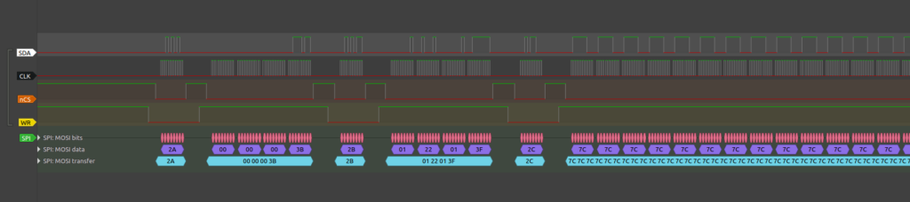
Here is what bitmap transmission through SPI looks like. Let’s assume we send a bitmap in a rectangle with coordinates (X1, Y1, X2, Y1):
- CD goes to 0, we want to send a command
- 0x2A (Column Address Set, CASET) is sent on SPI bus
- CD goes to 1 to send data
- Coordinates X1 are X2 are sent on SPI bus
- Similarly, 0x2B (Page Address Set, PASET) is sent, followed by coordinates Y1 and Y2
- Then 0x2C is transmitted, followed by all the bitmap bytes.
Complete protocol is described in ILI9341 datasheet.
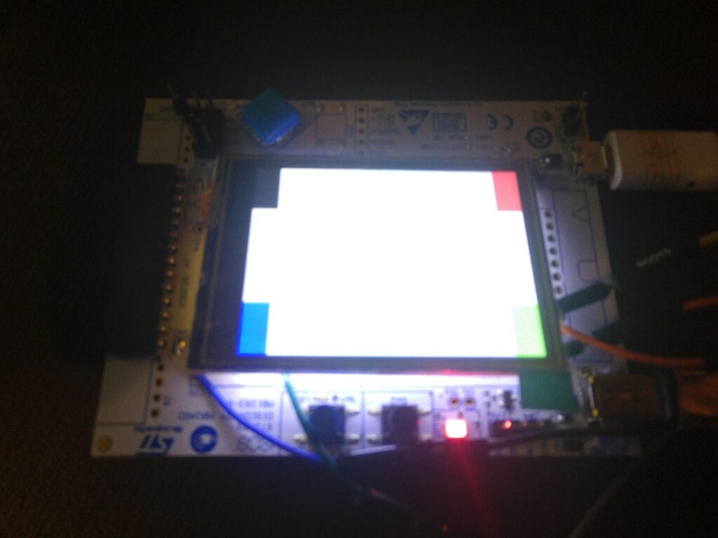
“Display” sample
Display is configured, it is time to test that everything works with a small but highly useful sample, samples/drivers/display.
Resistive touchpad
This display is not only a display, it also features a touchpad, albeit a resistive one. Smartphones got us used to capacitive touchpads, based on indium (ITO), and I had forgotten about this older and less sensitive tech. It does not contain any super-rare metals, which is cool. Although the physical, clickety buttons appeal more to me, I add my touchpad to device tree.


&i2c1 {
        pinctrl-0 = <&i2c1_scl_pb6 &i2c1_sda_pb7>;
        pinctrl-names = "default";
        status = "okay";
        clock-frequency = <I2C_BITRATE_FAST>;

        stmpe811: stmpe811@41 {
                compatible = "st,stmpe811";
                status = "okay";
                reg = <0x41>;
                int-gpios = <&gpiob 5 GPIO_ACTIVE_LOW>;
                [...]
        };
};
boards/arm/st25dv_mb1283_disco/st25dv_mb1283_disco.dts
The reader got that we got SCL on pin I2C1_SCL PB6, SDA on pin I2C1_SCL PB7, and interrupt GPIO on PB5.
I2C address
But how should we find this 0x41 address value? I got it from copy-pasting, but let’s still find it on STMPE811 datasheet.
| ADDR0 | Address |
| 0 | 0x82 |
| 1 | 0x84 |
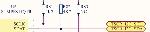
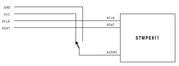
ADDR0 is either connected to GND (logical 0) or to VCC (logical 1). This is is given by the schematics: we need to check what is connected to ADDR0. Problem: we don’t have any ADDR0 pin, the closest match is something called A0/DATA_OUT. Back to datasheet, A0/DATA_OUT is described like this:
| Pin | Name | Function |
| 3 | AO/Data Out | I2C address in Reset, Data out in SPI mode (VCC domain) |
A0 is described as “I2C address”, so A0 and ADDR0 are two names for the same pin.
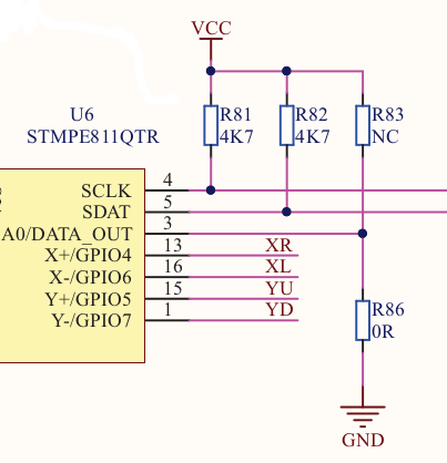
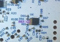
R83, between AO and VCC, is marked as “NC”, aka “Not Connected”, so there should be no component stuck here. I can verify that my schematics is accurate on my board:
R86, between AO and GND, is a 0 Ω resistor, same as a wire, so ADDR0 is 0.
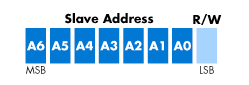
Our DTS I2C address is 0x41, and not 0x82. Why? Because in Zephyr RTOS, like in Linux, we use 7-bits I2C addresses, when in our datasheet 8-bits addresses format is used. In 8-bit, LSB is always a read/write bit. The driver will actually use both 0x82 for write and 0x83 for read, but they are automatically selected from the 7-bit 0x41 “root”, 0x41 being 0x82 right-shifted of one bit.
Note: here, “@41” means @0x41, not 41 in decimal, same syntax as Linux device trees.
Bonus: I2C shell
There is a quick way to check I2C addresses: the shell provides a command to scan the I2C bus.
First, activate the shell and its I2C option:
CONFIG_SHELL=y
CONFIG_I2C=y
CONFIG_I2C_SHELL=y
game/prj.conf
Then, once connected:
uart:~$ device list
devices:
[...]
- i2c@40005400 (READY)
uart:~$ i2c scan i2c@40005400
0 1 2 3 4 5 6 7 8 9 a b c d e f
00: -- -- -- -- -- -- -- -- -- -- -- --
10: -- -- -- -- -- -- -- -- -- -- -- -- -- -- -- --
20: -- -- -- -- -- -- -- -- -- -- -- -- -- -- -- --
30: -- -- -- -- -- -- -- -- -- -- -- -- -- -- -- --
40: -- 41 -- -- -- -- -- -- -- -- -- -- -- -- -- --
50: -- -- -- -- -- -- -- -- -- -- -- -- -- -- -- --
60: -- -- -- -- -- -- -- -- -- -- -- -- -- -- -- --
70: -- -- -- -- -- -- -- --
1 devices found on i2c@40005400Interrupt level
Another detail, the PB5 interrupt, is it active low or active high? Datasheet says it’s open drain, but do not mention polarity.
| Pin | Name | Function |
| 2 | INT | Interrupt output (VCC domain), open drain |
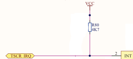
The electronics engineer did not forget the pull-up, so by default, this pin will be a 1. In software, it has to be active low.
If you configured stmpe811 output to be active high instead, you would force to 1 a line which was already set to 1, and it is an open-drain output, so logical 0 would be just leaving this line be… so it would be a 1 too.
| Logical level | 0 | 1 |
| Electrical level | 1 | 1 |
Datasheet also indicates that polarity has to be selected in INT_CTRL register (0x09):
[2] INT_POLARITY: This bit sets the INT pin polarity
1: Active high/rising edge
0: Active low/falling edge
Default register value is 0x00, so 3rd register bit would be 0, I only want to check that the driver does not change this value to invert polarity.
In STMPE811 driver:
#define STMPE811_INT_CTRL_REG         0x09U
[...]
#define STMPE811_INT_CTRL_BIT_GLOBAL_INT BIT(0)
[...]
    /* Enable global interrupts */
    err = i2c_reg_write_byte_dt(&config->bus,
                  STMPE811_INT_CTRL_REG,
                  STMPE811_INT_CTRL_BIT_GLOBAL_INT);
[...]
zephyrproject/zephyr/drivers/input/input_stmpe811.c
We write “BIT(0)”, aka 1, in the register, and the other bits are 0, including our 3rd bit. The driver agrees to be active-low.
In order to request input source file compilation:
CONFIG_INPUT=ygame/prj.conf
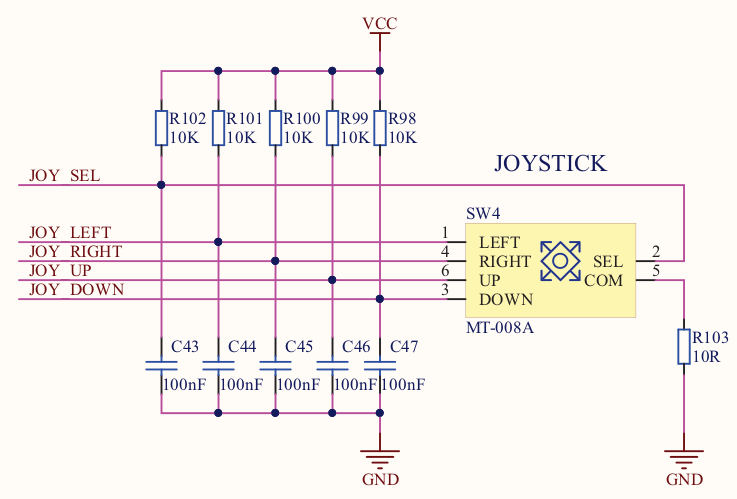
This is not actually a joystick, it is not analog, but it is a clever little push button with 4 directions and 1 vertical click.
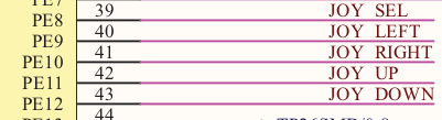
        buttons: gpio_keys {
                compatible = "gpio-keys";
                sel_button: button_2 {
                        label = "Sel";
                        gpios = <&gpioe 8 GPIO_ACTIVE_LOW>;
                };
                left_button: button_3 {
                        label = "Left";
                        gpios = <&gpioe 9 GPIO_ACTIVE_LOW>;
                };
                right_button: button_4 {
                        label = "Right";
                        gpios = <&gpioe 11 GPIO_ACTIVE_LOW>;
                };
                up_button: button_5 {
                        label = "Up";
                        gpios = <&gpioe 10 GPIO_ACTIVE_LOW>;
                };
                down_button: button_6 {
                        label = "Down";
                        gpios = <&gpioe 12 GPIO_ACTIVE_LOW>;
                };
        };
boards/st25dv_lvgl.overlay
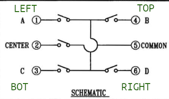
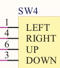
Wait, PE11 is named JOY_UP in schematics and “right” in my DTS, and PE10 is JOY_RIGHT and “up” in DTS. The error is not in DTS but in the schematics component, with this datasheet. If we decide that pin A is “LEFT”, because we are free to place this component as we want in our board, pin order will be LEFT, UP, RIGHT, DOWN, and it matches A(1), B(4), D(6) et C(3).

We can also tell Zephyr which keyboard code are associated to our pins with zephyr,code.
#include <zephyr/dt-bindings/input/input-event-codes.h>
[...]
                left_button: button_3 {
                        label = "Left";
                        gpios = <&gpioe 9 GPIO_ACTIVE_LOW>;
                        zephyr,code = <INPUT_KEY_LEFT>;
                };
boards/arm/st25dv_mb1283_disco/st25dv_mb1283_disco.dts
Those codes are mostly the same as in Linux standards, if you launch “evtest”, you will see code 103 (KEY_UP) and code 108 (KEY_DOWN), in decimal this time.
In zephyrproject/zephyr/include/zephyr/dt-bindings/input/input-event-codes.h :
#define INPUT_KEY_LEFT 105 /**< Left Key */
#define INPUT_KEY_DOWN 108 /**< Down Key */
zephyrproject/zephyr/include/zephyr/dt-bindings/input/input-event-codes.h
In order to compile drivers, we set the prj.conf:
CONFIG_GPIO=ygame/prj.conf
Bonus: GPIO shell
The shell is very helpful to debug GPIO issues.
First, activate shell and options:
CONFIG_SHELL=y
CONFIG_GPIO=y
CONFIG_GPIO_SHELL=y
game/prj.conf
Once connected:
uart:~$ gpio info
Line         Reserved Device           Pin
                         gpio@40020000     0
                         gpio@40020000     1
                         gpio@40020000     2
                         gpio@40020000     3
[...]
I do not know register addresses by heart, but this is easy to find in the datasheet or in the pre-built DTS, zephyr.dts.pre:
   gpioc: gpio@40020800 {
    compatible = "st,stm32-gpio";
    gpio-controller;
    #gpio-cells = <2>;
    reg = <0x40020800 0x400>;
    clocks = <&rcc 0x030 0x00000004>;
   };
build/zephyr/zephyr.dts.pre
I want to check that I have the right GPIO and level for my blue button:
gpios = <&gpioc 14 GPIO_ACTIVE_LOW>;boards/arm/st25dv_mb1283_disco/st25dv_mb1283_disco.dts
With button released:
uart:~$ gpio get gpio@40020800 14
1
I use gymnastics to simultaneously press the blue button and invoke the shell command:
uart:~$ gpio get gpio@40020800 14
0
My button setup is correct!
LVGL, the middleware
Plumbing and pseudo-drivers
Once hardware is set up, I wanted to try the graphical module everyone talks about, LVGL.
LVGL will find the display thanks to the zephyr,display we indicated, but we still have some pseudo-drivers to define to connect Zephyr system inputs to LVGL module.
#include <zephyr/dt-bindings/input/input-event-codes.h>
#include <zephyr/dt-bindings/lvgl/lvgl.h>

/ {
        pointer {
                compatible = "zephyr,lvgl-pointer-input";
                input = <&stmpe811>;
                invert-y;
        };

        keypad {
                compatible = "zephyr,lvgl-keypad-input";
                input = <&buttons>;
                input-codes = <INPUT_KEY_RIGHT INPUT_KEY_LEFT INPUT_KEY_UP INPUT_KEY_DOWN INPUT_KEY_ENTER>;
                lvgl-codes =  <LV_KEY_DOWN LV_KEY_UP LV_KEY_RIGHT LV_KEY_LEFT LV_KEY_ENTER>;
        };
};
boards/st25dv_lvgl.overlay
Small adjustments were made: invert-y puts the touchscreen in the same direction as the display. I also rotated buttons by replacing names.
As expected:
CONFIG_LVGL=ygame/prj.conf
But there are also lots of parameters to add to prj.conf for LVGL, as detailed to documentation and samples.
LVGL input drivers
LVGL selects touchpad as its default input, controlled by “zephyr,lvgl-pointer-input” pseudo-driver. Other input peripherals can be added, in my case, pseudo-joystick button is handled by keyboard driver, that you can activate with:
CONFIG_LV_Z_KEYPAD_INPUT=ygame/prj.conf
In order to test this, a small sample able to display digits and move around them with directional buttons: zephyrproject/zephyr/samples/subsys/display/lvgl
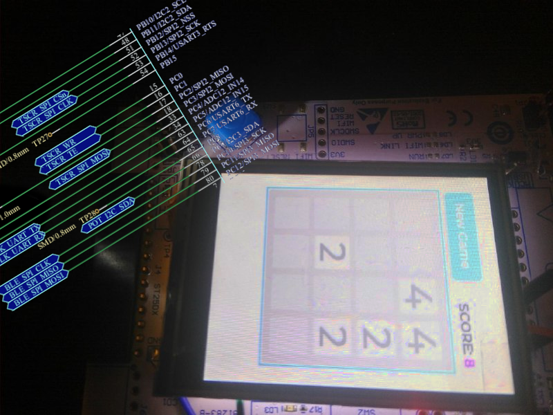
And now, an app
Now I can choose from all the existing LVGL app, I find a Github LVGL project with a 2048 game.
Several copy-paste and minor adaptations later, 2048 displays on my screen, but I only have touchpad control, and resistive touchpad swipe is not fun.
Button interrupts are received by my system, but I never jump in “lv_100ask_2048_event”, the LVGL application event handler. Yet, this function is ready to handle a push button even:
  else if(code == LV_EVENT_KEY)
    {
        game_2048->game_over = game_over(game_2048->matrix);
        if (!game_2048->game_over)
        {
            switch(*((uint8_t *)lv_event_get_param(e)))
            {
                case LV_KEY_UP:
                    success = move_left(&(game_2048->score),           game_2048->matrix);
                    break;
game/src/lv_100ask_2048.c
I was missing some lines:
    lv_group_t *btn_matrix_group;
    btn_matrix_group = lv_group_create();
    lv_group_add_obj(btn_matrix_group, game_2048->btnm);
    lv_indev_set_group(lvgl_input_get_indev(lvgl_keypad), btn_matrix_group);
game/src/lv_100ask_2048.c
Those lines create a widget group, add the main 2048 widget (game_2048->btnm), and link the new group with my input peripheral. And now it works, since button click events are transmitted to event handler.
Conclusion
I really wanted a Tetris…. but I learned cool new techs, I have a portable 2048, I got an excuse to go pestering the Zephyr community (many thanks to them!), I got my contributor badge, and I have an excuse to keep obsolete electronics in my drawer: it was a cool project.
Update: board was merged in mainline! You can now use “st25dv_mb1283_disco” from tree