


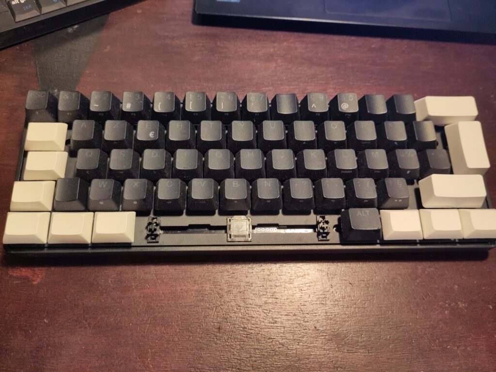
A while ago, I picked up a keyboard from a trash pile in the street.
It appeared to be a quality product, and it was, except it was very dirty and missing lots of keycaps.
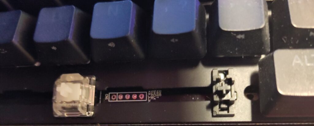
What also caught my eyes was the SWD debug header under the missing spacebar… I know the open-source keyboard community is very active, and after cleaning and adding some new keycaps, I could not resist trying to cook a new firmware for it.
So let us start by analyzing the board and its architecture!
1. Reverse-engineering
This keyboard has 62 keys on 5 lines, and each one has its own individual RGB LED.
1.1 Chip references
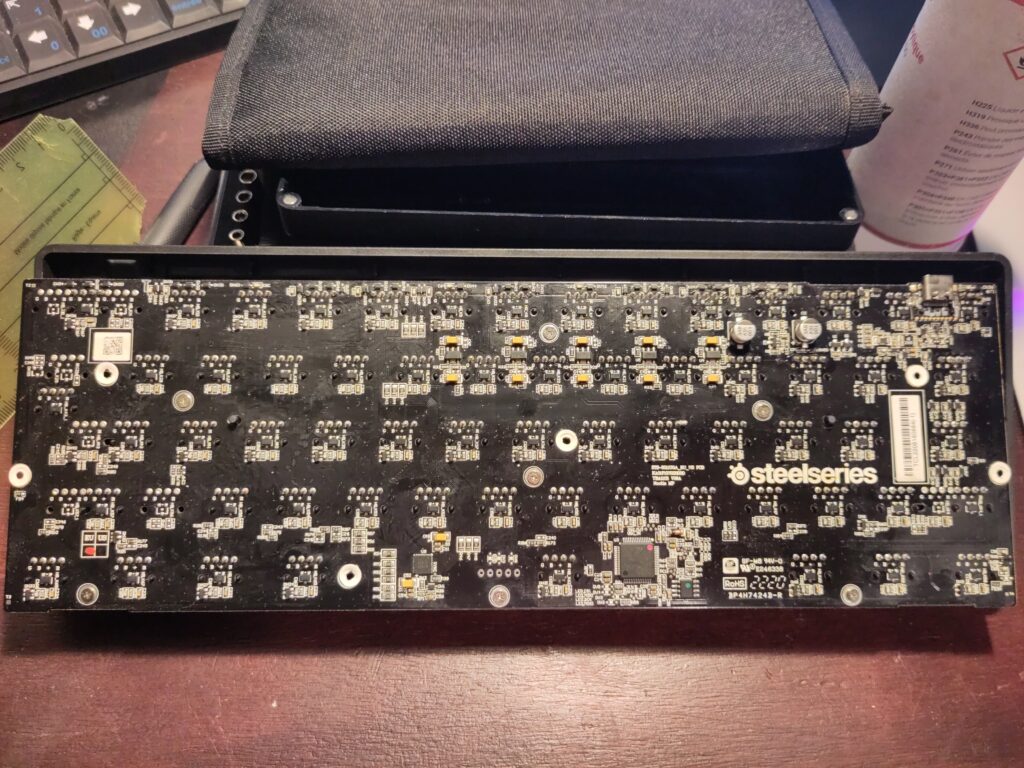
Getting my hands on a nice datasheet makes everything so much easier, so I spent a lot of time guessing the references.
The SoC is an STM32L412RBT6, easy to find out since it is written on it. The flash reference was also easy to read.
I struggled to find the LED controller reference.
This chip has pins accessible to probing, even if it is not very practical due to their tiny size. Probing could also short the pins, so you have to make sure everything is turned off before doing this kind of work.
With my multimeter in continuity mode, aka beepy mode, I checked that the chip outputs connect to LED lines, and that it connects to the SoC via SPI – I know it is an SPI bus because the testpoints are labeled LED_MOSI, LED_MISO, LED_SCK and LED_CS1.
The marking I read on the chip was “W1833 S7430”, but googling that gave no results.
I gathered some information to run a more advanced search for my reference:
- LED driver (because what else could be connected to all the LEDs)
- Connected with SPI (written on testpoints)
- 40 pins (4×10) (counted)
- Size around 5mm x 5mm size (measured)
- QFN-type package (dunno if there is a pad under this)
I started listing and filtering chips in catalogues distributors. I also tried feeding my chip description to ChatGPT, it answered a bunch of interesting references but not the one I was looking for. In order to verify if a references matches, the first thing I check is the pin disposition: for this driver, SPI and other non-LED pins are opposite to pin 1.
I ended up noticing that a company named Lumissil seemed to have several references that almost matched my description. It specializes in LED drivers, so I opened their full catalogue. Most of their products are I2C, so I filtered out all non-SPI references, and ended up finding the reference IS31FL3743 A and B chips.
They match my description… and then I understood I was misreading “S7430”: it was actually “3743B”. This chip is a Lumissil IS31FL3743B, and I need to buy a magnifier.

Lab shopping list item #1269: Soldering microscope
1.2 Pin connections untangling
After this, I used the datasheet and the multimeter to find out which LED is controlled by which pin. It took me a while and lots of beeps, but I ended up with a nice spreadsheet with all the indexes. The PCB overlay marking were very helpful: since each keyboard key has its reference marked, I can use them to not confuse any of the 62 keys.
For the keys pinout, it got a bit more complicated. First I read some keyboard schematics basics: they work in a matrix, with transistors, and most of the time diodes to prevent one keystroke to be detected as other keystrokes from the same line (or column). The little trick in my case is that the Schottky diodes are packaged by two, so there are only 3 diode chips per column, for 5 keys.
In order to help me a little bit finding connections, I also probed the keyboard live, with the oscilloscope: the keyboard scan has a pretty recognizable signal of 3ms period and 110us active-high pulse.
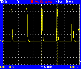
Row outputs on manufacturer’s firmware
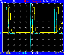
Superposition of 2 adjacent rows outputs on manufacturer’s firmware
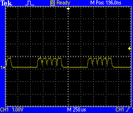
Scan signal noise on column input lines, no key press
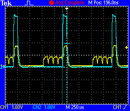
Key press on column input line (yellow), with row signal superimposed (blue)
After a good while I finally realized that each one of my rows was scanned by a signal, not directly from the STM32, but amplified beforehand, by a mystery component, maybe an op-amp. If someone recognizes this strange 6-pins package, with a bigger pin in the middle, please contact me.
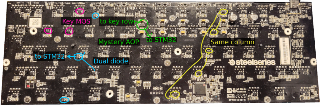
The STM32 pins connect to the input of my amp thingies for rows, and to the output of my dual diodes thingies for columns. This STM32 package pins can be comfortably probed to find continuity, still with the beep mode. So I ended up finding the whole matrix for keys too, and it is different than the matrixing of LEDs.
The full pinout is detailed here.
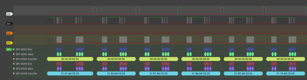
1.3 Protocol recording
Since I was not sure to be able to copy the factory firmware, I decided to record the communication between SoC and LED driver, even if I have full documentation on them and do not need to reverse-engineer the protocol itself. There are still some parameters and fine-tuning to retrieve.
Unfortunately, this means soldering on testpoints and I always damage stuff when I solder on testpoints.
I could not get the MISO line data, and my LEDs stopped lighting up. I damaged the poor LED controller in the process.
In case you are wondering how this should be done properly, the answer is probably probe holders.
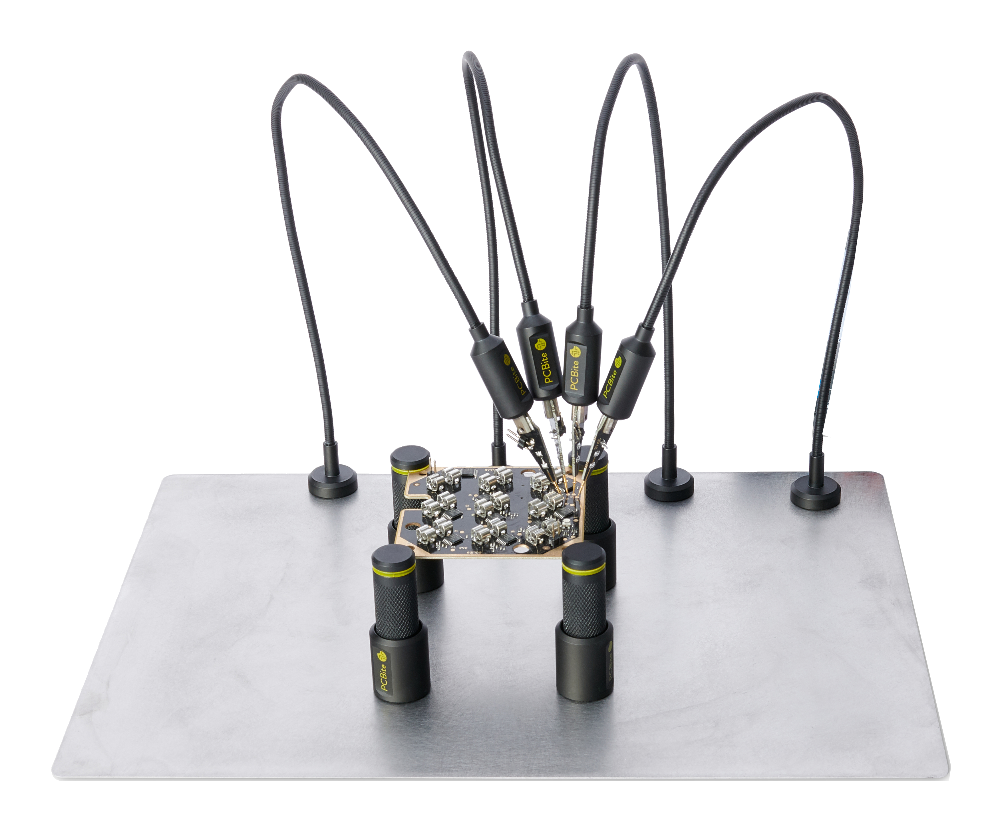
Lab shopping list item #1270: Probe holders
1.4 Software drafting
In order to make sure I had all the information I wanted before erasing all firmware from the board, I started drafting some software builds. I cloned the ZMK projects and started writing my device tree, which also forced me to complete my spreadsheet with some missing elements: the SPI lines for the flash, the USB lines, the testpoints… and I also started writing some documentation and creating branches for the project.
2. To brick or not to brick
Once I got all the useful information I wanted from the factory firmware, time to move on to the one-way operation: flashing a new firmware on the board. Or brick everything.
On STM32 chips, there are some read protections to prevent miscreants from reading the manufacturer’s firmware. Still, most of the time it is authorized to recover read/write access to the flash if you blank it first. This is controlled by the RDP option byte: “AA” means complete read/write access, and “BB” means no read/write access. Switching from BB to AA automatically resets the flash and send the manufacturer’s firmware to oblivion.
I opened my board with an ST-Link gizmo and the STM32CubeProgrammer software. It was detect and I could read the Option Bytes register. The board was in BB mode, so I switched to AA, thus destroying the existing firmware.
Then, I realized I could not write anything in the flash.
Oooops, I bricked it again?
After more reading and tutorial videos and playing with the option bytes, I managed to recover the read/write access. I was missing 2 things:
- For this chip family, there are read/write protection sets for memory ranges. In order to be disabled, one needs to write an end address before a start address, for instance start=0xFF and end=0x00.
- For those memory-range protections to be removed, one needs to set the “PCROP_RDB” bit to 1, and then to operate a transition from RDP BB to AA.
I had to switch my STM32 back to BB mode, change all the ranges without missing a field, check the PCROP box, and then switch again to AA mode. After several attempts (forgot to invert the ranges… forgot to tick the box…) I finally managed. Which means I can flash my new firmware, yay!
3. Writing a new firmware
3.1 Debugging the debug port
Of course, my draft firmware absolutely did not work at first try.
This board does not have connectors or headers for debug UART or even a nice debug LED on GPIOs, so I had to use the testpoints.
The first test I did was using Zephyr samples/basic/led to blink what actually was a testpoint, and probe it to verify the STM32 was alive and switching levels on the GPIO every second.
I tried to connect a GDB session but it failed, and I tried to debug my debugger… I just managed to fix a reset option in OpenOCD, which was good enough to get the board to flash with “west flash” instead of STM32CubeProgrammer. It was all I could do. Maybe a proper debug probe should be on the lab shopping list too?
I tried shell logging via USB but it failed, it needed to be debugged too. But in order to debug my USB logging I needed another form of logging.
I ended up soldering cables on testpoints again. I found some cool ones with the right pinmux to get me a debug UART.
I still don’t like this, I had to be careful while moving cables around, and I almost tore the testpoints off, but it was still worth it.
I began investigating the non-working USB, because USB is the only connection: it is the main feature, and it is also supposed to be my debug port.
Why it was not working:
- Clock. There is a special clock called HSI_48 to be enabled just for USB.
- Pincontrol. Since there is only one USB port, I did not think of adding a pincontrol, some models do not require you to. But since you could also use PA11 and PA12 as vanilla GPIOs it means that yes, the pincontrol is required.
After this, there were not so much more stuff left for me to get wrong.
&clk_hsi48 {
    status = "okay";
};

&usb_fs_phy {
    status = "okay";
};

zephyr_udc0: &usb {
    status = "okay";
    pinctrl-0 = <&usb_dm_pa11 &usb_dp_pa12>;
    pinctrl-names = "default";

    usbuart: cdc_acm_uart0 {
        compatible = "zephyr,cdc-acm-uart";
    };
};
After being corner-cased by the subsys/usb/testusb sample, which does not work on my platform in Zephyr version 4.2.99, I realized the other samples and the other versions were all working, and I ended up having a nice shell and log over USB.
3.2 Debugging the keyboard
3.2.1 First try
A first oscilloscope probing allowed me to find a first very obvious issue: my keystroke-probing signal was output on the column lines, which are supposed to be the inputs, and not on the row lines. Easy to fix by changing “col2row” to “row2col” in the device tree.
3.2.2 Second try
A second issue arose. Since the signal is amplified by an unknown gizmo, there is some filtering happening, and the 20us pulse provided by the ZMK driver gets eaten out by the hardware filtering. There is no signal left on the key MOS pins. It worked with the factory firmware because the pulse was 110us wide. So I need to increase the pulse duration.
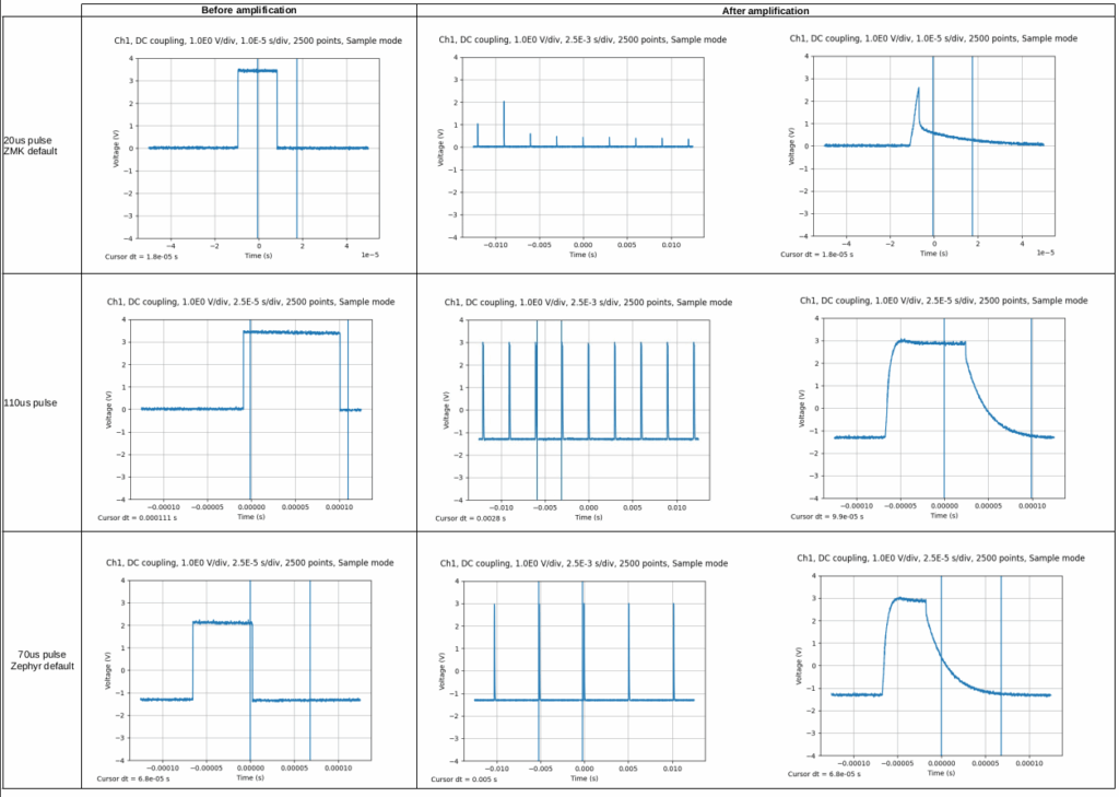
Comparing pulse sizes: why it does not works at 20us
My first measurements were done with a hack:
k_usleep(90); // Increase to 110 us pulseThen I asked about it on the ZMK Discord forum to get the right way to change the pulse. There is an option to add more time, in ticks (which are microseconds in my case) to the existing pulse, so 90 makes a 20us + 90us pulse:
CONFIG_ZMK_KSCAN_MATRIX_WAIT_BEFORE_INPUTS=903.2.3 Third try
Once this was solved, I ran my firmware, pressed a key, and it crashed. Started again, pressed another key, crash. Started yet again, waiting for a while, played with the shell, it was OK, pressed a key, crash. Disabled all the nodes and drivers I could from the device tree. Verified I was in polling mode and not in interrupt mode. Verified no other GPIO was colliding with my GPIO pincontrols. Disabled USB-UART CDC ACM mode and tried again with my testpoint serial port. Crash, crash, crash.
I tried to attach a GDB session to OpenOCD, again, and considered soldering a push-button to create a new reset button game like I do with all my STM32, where you have to find the exact moment to release the button otherwise GDB does not connect. Made a mental note to try to find a workaround for this STM32 reset button cult I have.
And then it hit me. I forgot Zephyr #1 rule, as I do each time I have this bug, I have to get it tattooed or get it on a poster or something:
Mysterious crash? Add more stack!
Actually it was not exactly as simple as that, I already added some more bytes to the application main stack, but the stack that provoked the crash here was not the usual stack, it was another stack:
CONFIG_SYSTEM_WORKQUEUE_STACK_SIZE=2048There! No more crashes. I finally managed to get some keys working, but not all keys, and they were definitely not typing the right letter.
3.2.4 Fourth try
First, the missing keys: I had a whole row missing, and could not understand why. I probed the signals, they looked fine. But I got tired and needed the win so I just added a fake row. Row number 0 is now an unused testpoint pin, and my actual keyboard rows start at one. It works.
3.2.5 Fifth try
One final detail: keys are working but they need to output the right keycode value. There are quite a bit of arrays to provide to ZMK, which I converted from my spreadsheet to my device tree thanks to my VIM search and replace expertise.
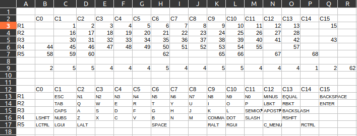
An glimpse into the spreadsheet from Hell
First you have a zmk,matrix-transform object that maps the hardware coordinates of the key to an index of a list that should match your mechanical layout. Since the list is 1D and not 2D you have to get a precise idea of which key belongs to which line. Also, I have a weird ESC key that is on the first line physically on the layout, but is on the 5th line on the electrical matrix: this is where it gets fixed. Then this new “fake 2D” array has to match a keymap file, of type zmk,keymap, with the same indexes, which describes which keyboard codes are sent.
I am French and this keyboard is AZERTY, so I thought the keyboard codes would be AZERTY, but no. After I ran evtest on my own computer keyboard, I realized even the AZERTY keyboards do not send AZERTY keycodes: they send QWERTY and it is translated to AZERTY by the system. My “M” key is actually sending the SEMICOLON keycode. So I rewrote the keyboard codes in QWERTY, based on my own keyboard and a picture I have of the US version of the Apex Pro Mini, and got most of the matrix right. Except for my “><” key, which is called KEY_102ND on Linux, as reported by evtest: it does not exist on QWERTY keyboards. The ZMK name for it is: NUBS (Non-US BackSlash), and Zephyr calls it INPUT_KEY_HOME as per input-event-codes.h.
The ENTER key is 2 rows high, I had to choose a reference row for it. And choose the same in every file, because since the array is 1D, one mistake for a key position offsets all the other following keys. But a wrong keyboard matrix is great fun to debug.
So finally, the keyboard works with ZMK powering it. You can find the ZMK source code here.
3.3 Additional fun with the SPI flash
I have an SPI flash, so let’s try to talk to it with the samples/drivers/spi-flash sample code.
The sample could not initialize my flash. A quick multimeter check gave me a chip select pin staying at 3V3, so my chip was never selected… As an experiment I forced it to zero by declaring it as an LED and using gpio_pin_set_dt. After forcing my GPIO it worked. Why oh why do the CS pins never work with me?
I think I finally figured out why. CS pins can be controlled by the SPI peripheral, which is why you get pin controls such as “spi1_nss_pa15” and “spi2_nss_pb12”, but in Zephyr the SPI drivers use them as vanilla GPIO, not invoking them through the SPI peripheral, which makes sense too. So if you get overzealous and invoke the CS pincontrols like I do, you are actually preventing Zephyr from using them as normal GPIOs. No pincontrols for CS, they just go in the cs-gpios field and the driver manages.
Also, USB CDC ACM requires several Kconfig options to work, like CONFIG_CDC_ACM_SERIAL_INITIALIZE_AT_BOOT. There is a magic config invocation file to make it all work: boards/common/usb/Kconfig.cdc_acm_serial.defconfig.
So finally, my SPI flash works too!
Conclusion
Several years ago, I watched a video about installing OpenWRT on old routers, and its conclusion was: “DIY electronics kits are cool, but the best thing is reusing hardware you already have”. It really opened my mind. I have been meaning to achieve this kind of hacking and upcycling project for a long time, I am very happy about how it turned out!