


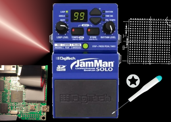
A friend gave me this guitar loop pedal, a Digitech JamMan Solo (released circa 2010), to try and repair.

The pedal did not start. Its main LED lighted on for 3 seconds at boot, and then, nothing else happened. I plugged it to my computer and no USB was enumerated. Since nothing seemed wrong at first glance, I opened the gear and found this Atmel SAM9G45-based architecture.
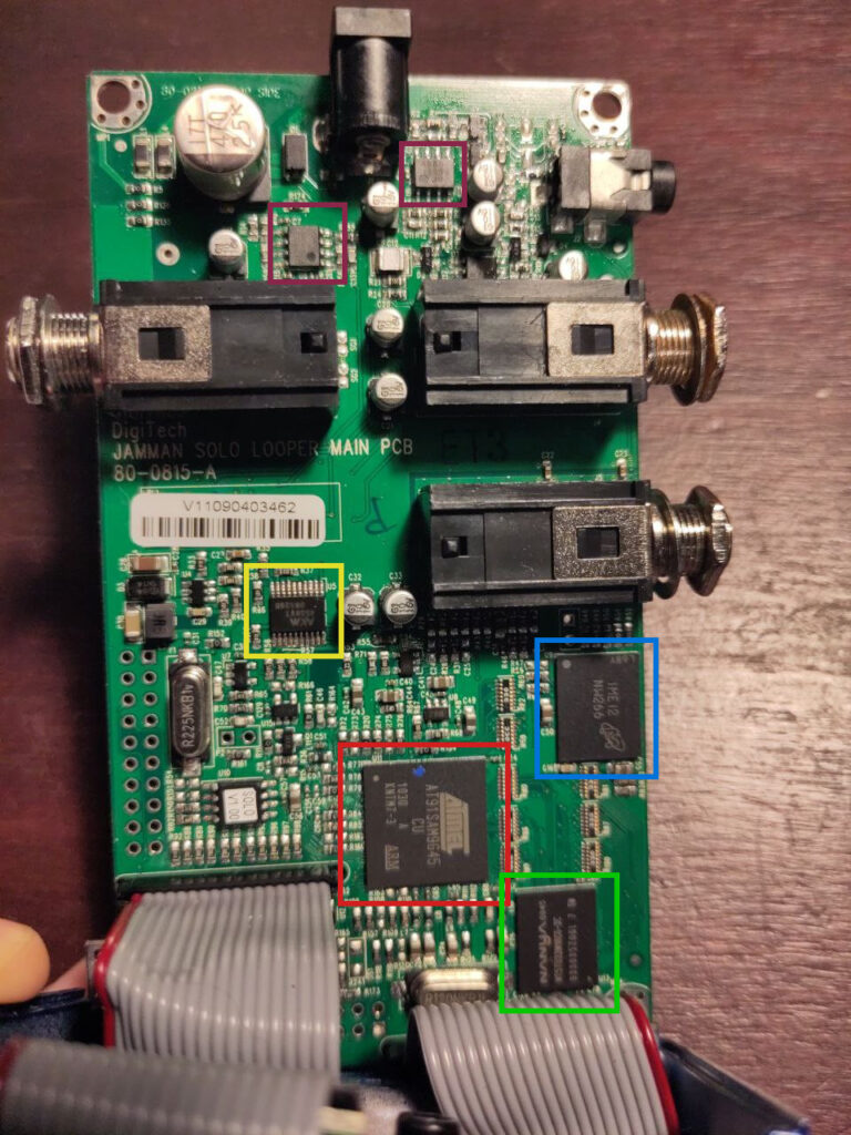
Main components
- Atmel AT91SAM9G45
MPU with ARM926EJ-S 400 MHz ARM Thumb Processor - Micron NW266
NOR Flash - Nanya (Kynix) NT5TU32M16C6
DDR2 SDRAM 32Mx16 - AKM AK4556VT
Audio stereo codec 24bits - HMSemi JRC4580
A bunch of audio-quality operational amplifiers
After checking nothing burnt and all power supplies were present, I moved on to figuring out whether the processor was alive or dead.
A note about the music gear 9V power supply
In the music gear world, the standard power supply is DC 9V over a 5.5mm / 2.1mm barrel jack… but beware, because the barred jack is connected with the + outside of the barrel and the – inside!

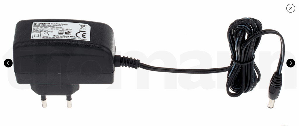
Those adapters have to be used with caution. I measured my amplifier’s one and found a solid 11.5V output instead of the expected 9V.
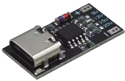
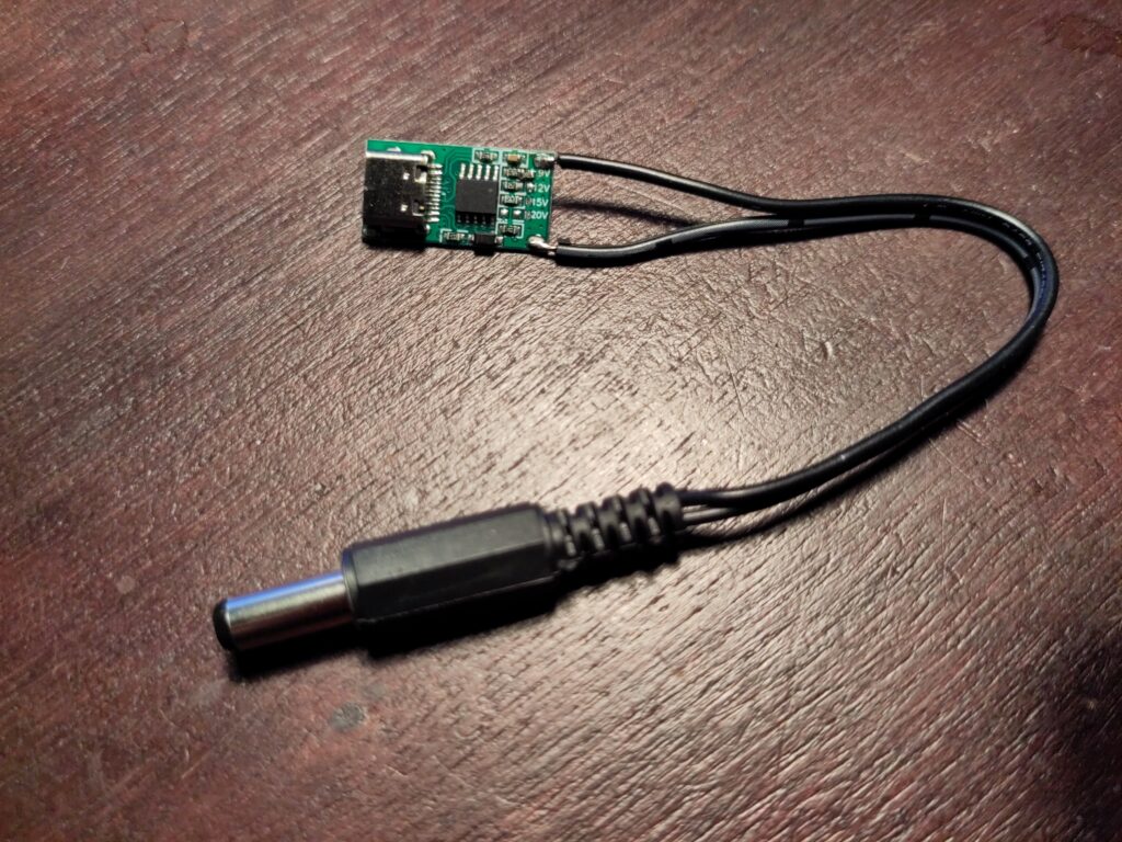
In order to get a real 9V, I like to use USB-C power delivery, since 9V is among the possible voltages. You can find small USB power delivery decoy boards from your favourite Chinese supplier, on which you solder bridge to get the voltage you want. This is how I manufacture my own USB-C to guitar pedals power adapters.
Where are the debug ports?
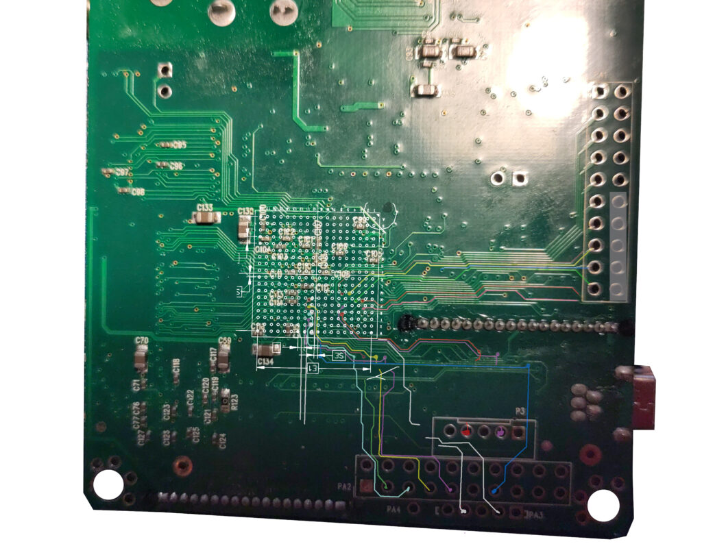
A quick look at the board
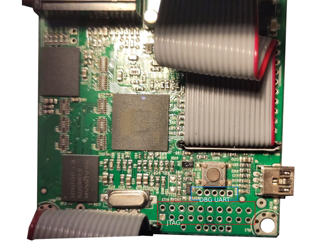
This board has lots of through-hole connectors, but none of them is annotated.
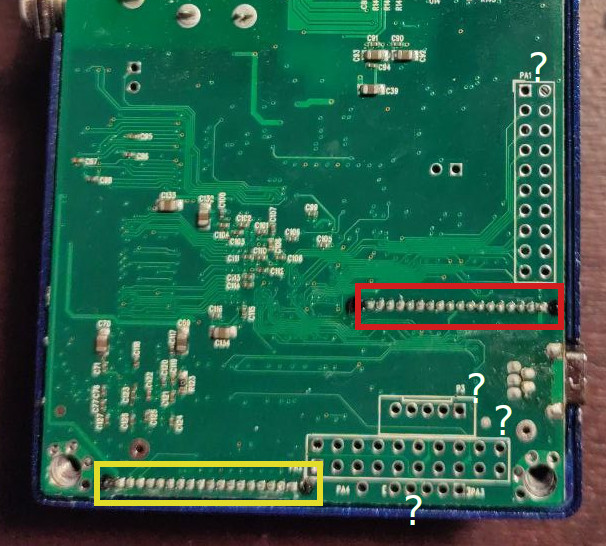
- Connector to SD Card
- Connector to UI board (display, buttons…)
So, how do we find the JTAG and debug UART ports?
Fun with Gimp
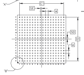
I took photographs of top and bottom, and a screenshot of the BGA footprint from the datasheet, and imported it all in Gimp for image manipulation.
First I aligned top and bottom: I trimmed the board edges for reference, mirrored top, and used the “Unified Transformation” to resize and reshape the two images.
Then I used top layer to fit the screenshot of the BGA footprint, making sure I have it on the right side. It is a bottom view in the datasheet and my reference is bottom, so I did not need to mirror this one. I also rotated it to match the pin 1 indicator placement.
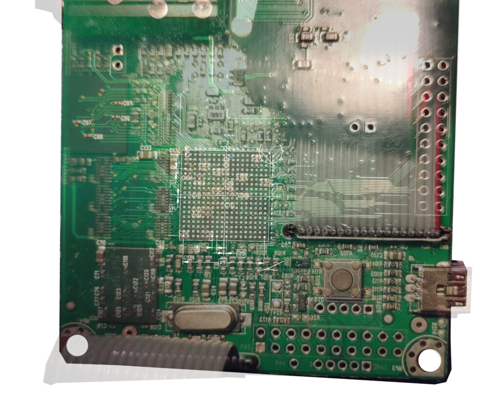
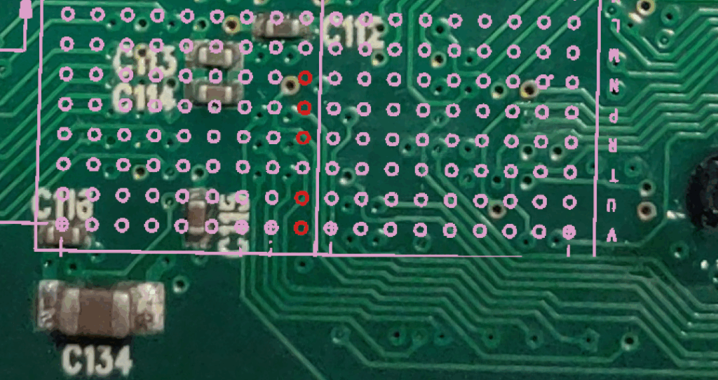
Once this is done, if I hide the top layer picture, I can get a pretty good view of the BGA fanout. Of course this is not very precise because a same via could correspond to any of the 4 balls around it, but it greatly narrows down the possibilities.
Now I would like to verify my image layering. I usually use GND and power supply pins to do this type of checks, but this time the best option I found was the main clock tracks on the top layer.
According to the datasheet:
- Ball V11: XOUT
- Ball V12: XIN
We can see here that the tracks stop between V10 and V11, and V11 and V12, so it is easy to imagine they just continue a little bit to the left under the BGA. It seems to be matching!
Hunting for debug ports
Since the board has lots of connectors, I decided to start the detective work from the ports I wanted to find. First, the JTAG port.
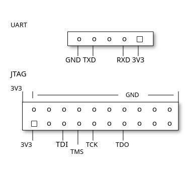
- NTRST = N10
- TMS = P10
- TDI = R10
- TCK = U10
- TDO = V10
The JTAG ports are all aligned in column 10. We can see a bunch of tracks starting around here, let’s go follow them.
I created a nice new layer with some transparency and started highlighting the surrounding tracks. But hey, they are going into vias! I hope this design does not have signals in internal layers so I can catch them back on the top layer.
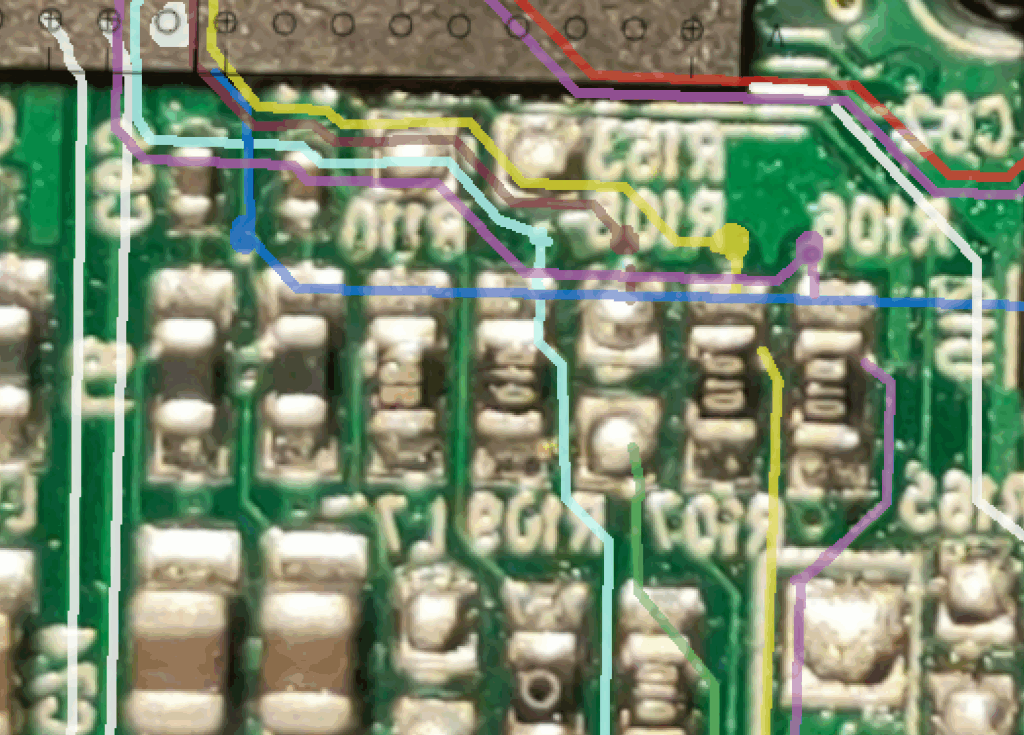
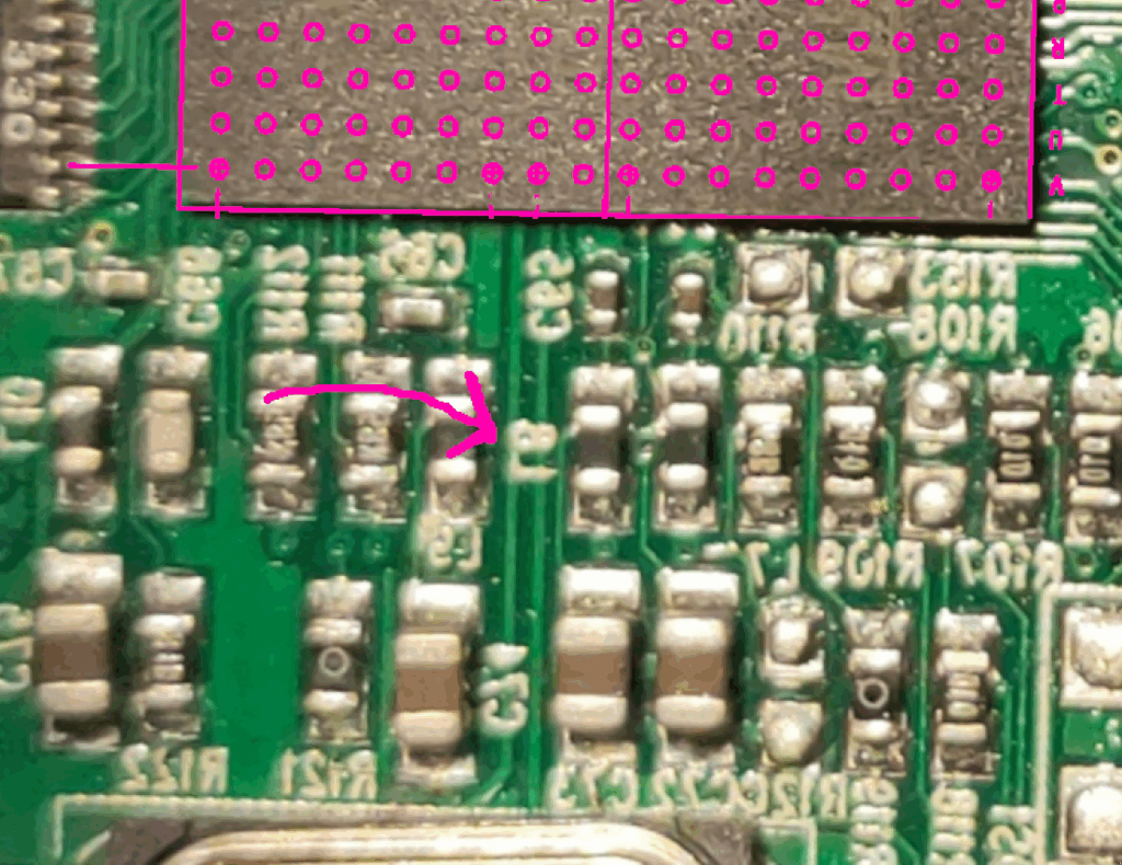
Here we have a top layer where our signals emerge from vias, and seem to be finding some pull-up resistors. The red one is not equipped, the other ones are. It is a special cookie, the only optional one, which gives a good hint of which net it is.
And we finish our path on top layer on this nice connector, which is not a 2.54mm but a 2mm header.
For the purple track, since it was not visible all the way long, I used the multimeter in continuity mode. After reaching R106, it is indeed going to the connector, but it is hidden by the D21 overlay marking.
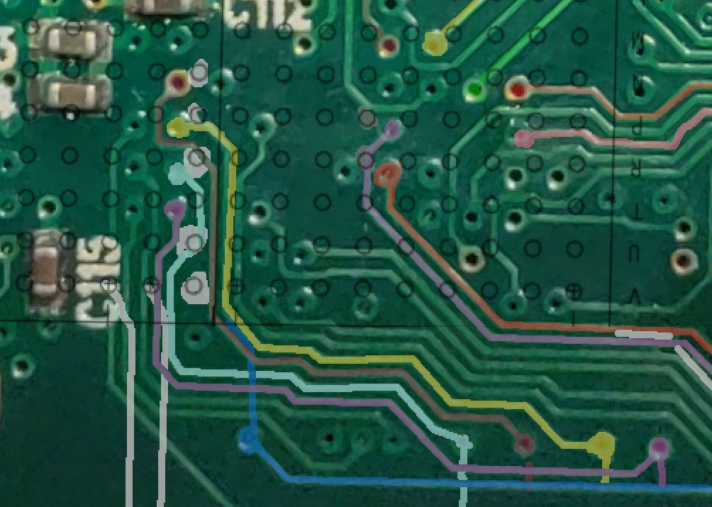
There is not a lot of possibilities, because we have found 5 signals and need to fit 5 JTAG nets, so my hypothesis is this one:
- NTRST = N10 Red and green, with a non-equipped resistor
- TMS = P10 Yellow
- TDI = R10 Light blue
- TCK = U10 Purple
- TDO = V10 Dark blue
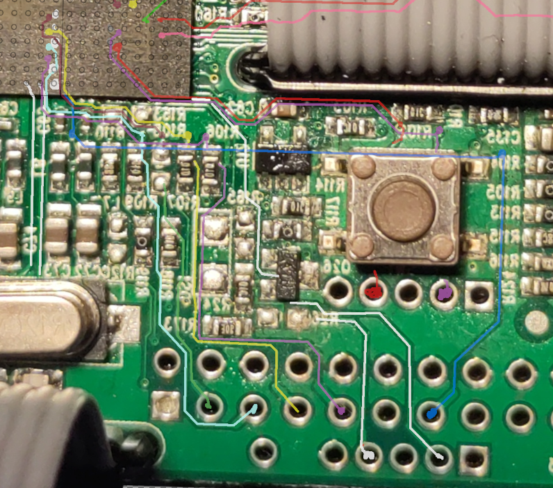
I also drew a red and a purple track going under the button, those tracks start close to my debug BGA balls:
- DRXD on PB12 = P6 ball (Purple)
- DTXD on PB13 = R6 ball (Red)
Fortunately I did not need to desolder the button to verify where those tracks were going, because a bit of probing gave me a beautiful TX signal on board boot on the connector pin.
Pinout
It’s alive!
After soldering my wires to plug a good old USB-UART converter at baud rate 115200, I got a console log at board reboot.
> screen /dev/ttyUSB0 115200
QNX Neutrino Initial Program Loader for JamManSolo ATMEL AT91SAM9G45
ATMEL AT45DB321D SPI Flash detected.

QNX IFS image detected on page: 00000020 Offset: 00000000 Size: 00137E7C

###################Done

found image, calling image setup…
image_setup OK, calling image start…

PIO init : DBGU, NAND, EMAC.
Welcome to QNX Neutrino 6.4 on the JamManSolo Atmel AT91SAM9G45
Starting DBGU driver…
fs-etfs-at91sam9xx: Yes this is you !!!
fs-etfs-at91sam9xx: id[1] = ba
fs-etfs-at91sam9xx: devio_init: Flash ID: Manufacturer ID=0x2c, Device ID=0xba
/mnt/nandfs/lib/fs-dos.so
So we are running some Blackberry QNX.
It seems to have some trouble at boot:
ldd:FATAL: Could not load library libUniString.so
ldd:FATAL: Could not load library libUniString.so
I suspect the NAND flash, containing the QNX system files, got corrupted somehow.
Good news, it has a prompt! I can interact with things!
Repair attempts
Firmware update
User update can be done by copy-pasting the installation firmware file on the SD card, then at boot the device automatically installs the file if present. But I could not reinstall the system because the firmware update file was nowhere to be found. I found a nice Facebook community where a bunch of people tried asking the manufacturer for help, with no answers from their part. What a shame!
Manual rewriting
Copying the firmware
QNX has some Unix-like commands and file directory, so let us play a bit with it.
We can find 2 memory storage: one is a standard SD Card, which can be removed from the device and read on a computer, the other is a soldered NAND chip, whose content is apparently damaged.
# ls /mnt/
nandfs     sdfs
# ls /dev/
console hds name sem slog stdout tymem
etfs1 hds1 null ser1 stderr text zero
etfs2 mem pipe shmem stdin tty# df
/dev/etfs2 508928 83572 425356 17% /mnt/nandfs/
/dev/etfs2 512904 512904 0 100% (/mnt/nandfs/)
/dev/etfs1 15480 15480 0 100% I can use the etfscl command, we can get info on the memory (etfs1 is for bootloader and raw binaries, etfs2 is the filesystem):
# etfsctl -d /dev/etfs1 -i
Device NAND2cba
   Blocks     Clusters/Block Clustersize            Totalsize
         2048             64        2048            268435456
[...]
# etfsctl -d /dev/etfs2 -i
Device NAND2cba
   Blocks     Clusters/Block Clustersize            Totalsize
         2048             64        2048            268435456
[...]
Copying files (-r for structured, -R for raw):
# etfsctl -d /dev/etfs2 -r /mnt/sdfs/etfs2
# etfsctl -d /dev/etfs1 -r /mnt/sdfs/etfs1
# etfsctl -d /dev/etfs1 -R /mnt/sdfs/etfs1raw
# etfsctl -d /dev/etfs1 -R /mnt/sdfs/etfs2raw
# dd if=/dev/mem of=/mnt/sdfs/mem.img
dd: /dev/mem: Server fault on msg pass
14336+0 records in
14336+0 records outThere is a -w / -W function to copy from file.
I can also copy the content of the nandfs partition:
# cp -r /mnt/nandfs/* /mnt/sdfs/nandfs
cp: read (nandfs/JamManSolo/Patch22/PhraseA/phrase.wav): Input/output error
cp: read (nandfs/boot/dhcp.client): Input/output error
cp: read (nandfs/boot/io-pkt-v4): Input/output error
cp: Can't get file status (nandfs/boot/libcam.so): No such file or directory
cp: read (nandfs/usr/audio/JamManSolo/Patch09/PhraseA/phrase.wav): Input/output error
[...]
cp: read (nandfs/usr/audio/JamManSolo/Patch02/PhraseA/phrase.wav): Input/output error
cp: read (nandfs/usr/lecmd): Input/output error
It is weird that some files give errors while I try to copy them.
Almost fixed… but not
So, someone took the the time to copy the content from an operational pedal, along with his logs, and I know have files to try and fix mine.
First, I analyzed the files and logs with diff, vimdiff, hexdump and tree. Interestingly, some files are missing.
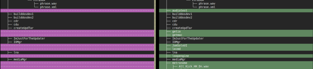
Left: broken pedal filesystem copy, right: normal pedal
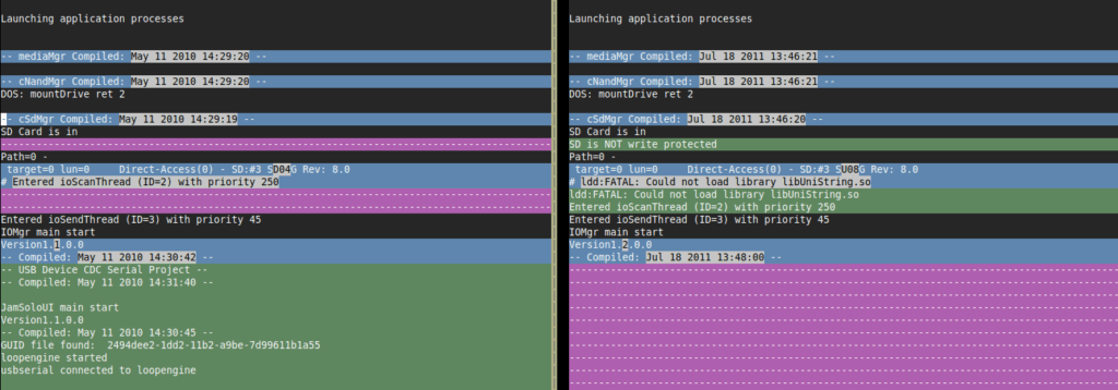
Left: normal pedal boot log, right: broken pedal
I checked one or two libs with diff to check if the broken pedal and the new could use the same binaries, and the lib files are exactly identical. This is very good news.
diff broken/nandfs/lib/libWavWriter.so ok/nandfs/lib/libWavWriter.so
<No diffs>
diff broken/nandfs/lib/libc.so.2 ok/images/nandfs/lib/libWav/libc.so.2
<No diffs>
I then tried to copy only the files that failed with cp or that I found in fail logs. For instance, when the UI tries to load:
# /mnt/nandfs/usr/JamSoloUI
ldd:FATAL: Could not load library libUniString.so
The diff on this file shows there are not the same, which is suspicious.
$ diff files_broken_jamman/nandfs/lib/libUniString.so files_pristine/images/nandfs/lib/libUniString.so
Les fichiers binaires files_broken_jamman/nandfs/lib/libUniString.so et files_pristine/images/nandfs/lib/libUniString.so sont différents
I copied this file from the working pedal files, and it got better! The UI application and the USB CDC are now loading.
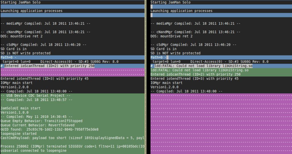
Left: boot log with new library copy, right: initial boot log
Then, since the USB CDC has started, my device gets USB enumeration. So I tried updating the app through the official application. The device was detected, but the update still failed. Then I tried to copy all the NAND files, in case I missed one:
cp -r /mnt/sdfs/nandfs/* /mnt/nandfsFinesse failed: moving on to violent erase and rewrite
So since the device was still not usable, it was time to rewrite everything. Per etfsctl documentation, rewriting requires to erase the drive first.
# etfsctl -e
Error status on option 'e' : Resource busy
So I killed apps, and erased the memory etfs2. And now the SD card is not mounted anymore, maybe I erased the SD card driver too… Which is a huge problem since it contained the image I wanted to copy from. Oops…
Fortunately it still worked after a reboot, and the SD card could mount again. The proper way to do this would be to store this somewhere safer before erasing etfs2.
After reading the etfs documentation more carefully, I realized that the following command handles the system stop and restart, the erasing, and the rewriting processes (every option switch is important here):
etfsctl -d /dev/etfs2 -S -e -w /mnt/sdfs/etfs2.structured.bin -cAnd voilà! After a reboot, the pedal started working again.
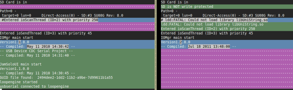
Left: boot log after fix, right: initial boot log
Conclusion
Disclaimer: do not be fooled by the survivorship bias, most of my repair attempts end up in failure, bitterness, and regrets.
If you want to repair stuff:
- Never be afraid to break something that is already broken
- Just keep trying, no matter how many times you fail
You may notice I did not even have to use the JTAG port, so maybe the BGA reverse-engineering was overkill. But it was really fun to do and I think I will reuse this technique in the future.
This was also a perfect opportunity to create a new iFixit tutorial!