


Now that you know everything on display modules, controllers, and what you can buy on the market thanks to my previous article here, let us see in details how to add it to your project with an example.
Here is my use case: I have a DIY project for which I need an HMI. I need to display parameters, text, numbers, and maybe simple graphics. I want a cheap option and I don’t need anything fancy like RGB or animations.
Furthermore, I want out-of-the box Zephyr support, which leads to the next question: how do I know if a reference is supported or not?
Is my display module supported?
Need a controller reference
I found this NewVision X154-2864KLBTG01-C24 on LCSC, it is a monochrome 128×64 OLED display for less than 6 €, which is fine by me.
There is a display controller mentioned somewhere, you can play Where’s Waldo with the datasheet if you like games. Waldo looks like this:
Driver IC: SSD1309Click here to see the solution
On page 5, under the mechanical drawing, bottom left side “Notes” section if you turn the page in landscape mode.
So my controller is “SSD1309”, and a quick Internet search gives me its manufacturer name, which is Solomon, and its datasheet.
Yes, but is it supported?
Zephyr support can sometimes be tricky to determine.
The reason is that products are declined into product ranges, so, the same software driver can handle different products. You will have different scenarios:
- Wildcard driver names making things difficult. Solomon SSD1608 or SSD1681 support is provided by ssd16xx.c, so you will need grep to find if ssd1681 is actually mentioned somewhere.
> grep -rnwi ./ -e ".*ssd1681.*"
./drivers/display/ssd16xx.c:994:#if DT_HAS_COMPAT_STATUS_OKAY(solomon_ssd1681)- Your driver support has never been tested and is not anywhere to be found, but there is something pretty close that could be compatible. It sounds far-fetched, so why would it work?
- Manufacturers often use the same logic core and same register map when they create a range, just changing a few peripheral and memory things.
- Sometimes chips are updated and the reference is changed, but the global behaviour is pretty similar to the previous version.
In my care, grepping SSD1309 gave out nothing.
It does now, actually, but it was merged afterwards, so let’s pretend it does not exist.
There is an interesting file called ssd1306.c in the display drivers folder, that I found out by gradually removing numbers from the product number. Same manufacturer, same type of product: maybe luck is on our side.
grep -rnwi ./ -e ".*ssd1309.*"
grep -rnwi ./ -e ".*ssd130.*"
grep -rnwi ./ -e ".*ssd13.*"
grep -rnwi ./ -e ".*ssd1.*"
grep -rnwi ./ -e ".*ssd.*"
grep -rnwi ./ -e ".*s.*" // Despair
Okay cool, but is it supported?
So we got a driver that could maybe bring support for our controller.
The detective work is not over! We are now going to look for the SSD1306 datasheet, and compare it with SSD1309. Do you know the game of differences? Same here, but with register maps.
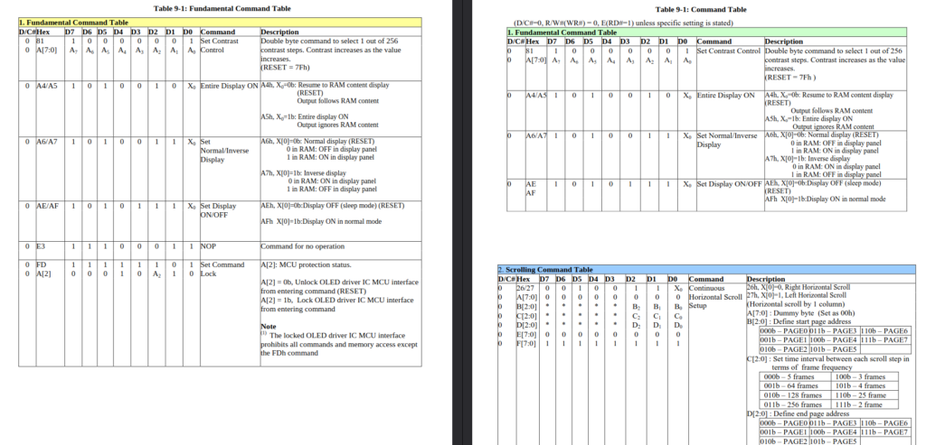
Left: SSD1309, right: SSD1306
For instance, we can see 0x81 is “Set Constrast Control”, and 0xA5 is “Entire display ON”, in both case. If most commands are identical in both products, the driver will most certainly be compatible.
Another technique consists in comparing the SSD1309 datasheet directly with the ssd1306 header file.
#define SSD1306_SET_CONTRAST_CTRL       0x81 /* double byte command */
#define SSD1306_SET_ENTIRE_DISPLAY_OFF      0xa4
#define SSD1306_SET_ENTIRE_DISPLAY_ON       0xa5
ssd1306_regs.h
I like to do a little bit of both.
Also, now that I have both datasheets, I can try to guess what is the difference between the two references. My guess is hidden, if you want to play detective yourself.
My guess
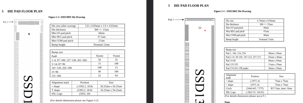
The die size is different, SSD1309 is smaller. Also, the datasheet release for SSD1306 is “Apr 2008” for SSD1306 and the one for SSD1309 is “Jul 2011”. So I would say it was re-printed with a more miniaturized tech.
But are you really sure it is supported?
In the first datasheet, the module one, we managed to find a controller reference. But is it reliable, not a typo or a deprecated information?
And what happens if there is no such reference in the datasheet?
And also, there is no register map section, so how do we know all the module specific parameters to put into the device tree?
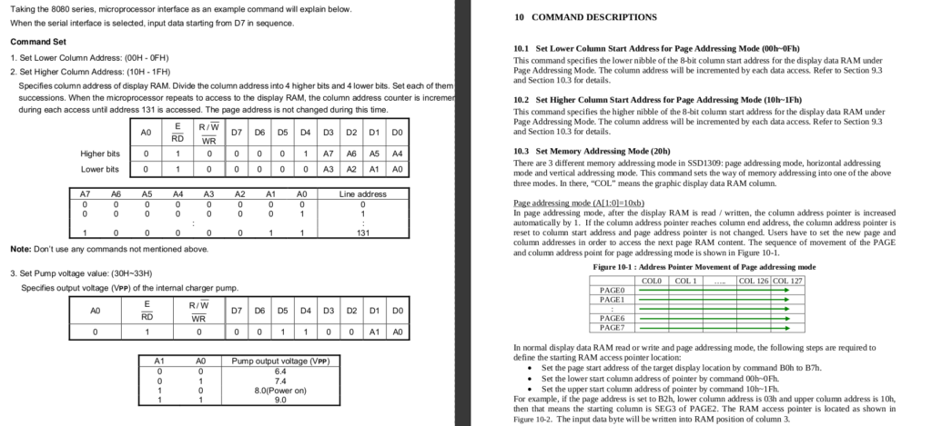
Look closely at the pseudo-code section on pages 20 and 21.
write_i(0x81); /* set contrast control */
write_i(0x32);
Here, the pseudo-code tells to set register 0x81, the one Zephyr names SSD1306_SET_CONTRAST_CTRL, to 0x32. You can decipher this pseudo-code with the SSD1309 datasheet and see if it makes sense.
ⓘ I have been doing a lot of CTRL-F search in PDF files. If you adopt this technique, remember that sometimes hexadecimal values are written “XXh” instead of “0xXX”, like here. So you have to look for 81h: “Set Contrast Control for BANK0 (81h)”.
I am now pretty sure that the SSD1306 driver will also apply to my SSD1309-based module!
Set up the device tree and driver configuration
The display has been chosen, the board has been designed, ordered and received, it is now time to actually configure and test the Zephyr driver.
Module-specific configuration
There are a lot of parameters to feed to the device tree, that will be specific to the module, for instance the display size and horizontality/verticality status.
For this we will get back to the pseudo-code provided by the display manufacturer. How do we convert it to Zephyr?
See full pseudo-code here
void SSD1309 ()
{
RES=0;
delay(1000);
RES=1;
delay(1000);
write_i(0xae); /* set display off */
write_i(0x00); /* set lower column start address */
write_i(0x10); /* set higher column start address */
write_i(0x40); /* set display start line */

write_i(0x81); /* set contrast control */
write_i(0x32);

write_i(0xa1); /* set segment remap */ 127 to seg 0, remapped = segment-remap
write_i(0xa6); /* set normal display */ A6 = normal, not reversed SET_SEGMENT_MAP_REMAPED SET_NORMAL_DISPLAY (bit inverse or not) inversion-on;

write_i(0xa8); /* set multiplex ratio */
write_i(0x3f); /* 1/64 */

write_i(0xc8); /* set com scan direction */ C8 = remapped SET_COM_OUTPUT_SCAN_FLIPPED com_invdir
write_i(0xd3); /* set display offset
write_i(0x00); */

write_i(0xd5); /* set display clock divide/oscillator frequency */
write_i(0xa0); /* clock div ratio */

write_i(0xD9); /* set charge period
write_i(0xF1); /* prechargep */

write_i(0xda); /* set com pin configuartion */ ?
left/right remap (A[4] et A[5] - Scan direction top or bottom (C0h ou C8h)
write_i(0x12); // Enable COM Left/Right remap (DAh A[5] =1)

write_i(0x91);
write_i(0x3F);
write_i(0x3F);
write_i(0x3F);
write_i(0x3F);
Configuration parameters
Let’s see this contrast setting again.
write_i(0x81); /* set contrast control */
write_i(0x32);- In ssd1306_regs.h, the 0x81 magic number is given a cool name, SSD1306_SET_CONTRAST_CTRL.
#define SSD1306_SET_CONTRAST_CTRL 0x81 /* double byte command */ssd1306_regs.h
- In ssd1306.c, the SSD1306_SET_CONTRAST_CTRL byte is written by the function ssd1306_set_contrast.
- This function is called at init by:
ssd1306_set_contrast(dev, CONFIG_SSD1306_DEFAULT_CONTRAST)ssd1306.c
CONFIG_SSD1306_DEFAULT_CONTRAST is a configuration parameter. It can be modified via any of your project Kconfig file, but I would suggest using the one living close to your dts file.
I can now add the recommended manufacturer value 0x32 to myboard.conf, in decimal, so it is a 50.
CONFIG_SSD1306_DEFAULT_CONTRAST=50myboard.conf
Device tree parameters
Another pseudo-code line states:
write_i(0xa8); /* set multiplex ratio */
write_i(0x3f); /* 1/64 */
Multiplex ratio is either width or height, minus one, depending on how your display is wired to the controller.
#define SSD1306_SET_MULTIPLEX_RATIO 0xa8 /* double byte command */ssd1306_regs.h
This time, the byte is written by the function ssd1306_set_hardware_config. It writes a value called config->multiplex_ratio, and config is from the driver API, the struct device config field. So, it is read from the device tree.
[...]
SSD1306_SET_MULTIPLEX_RATIO,
config->multiplex_ratio,
[...]
ssd1306.c
You can also find it in the driver bindings, and it is required:
multiplex-ratio:
    type: int
    required: true
    description: Multiplex Ratio
dts/bindings/display/solomon,ssd1306fb-common.yaml
Here is the 0x3f value I put in the device tree. It has to be decimal too, and 0x3f = 63.
ssd1306: ssd1306@0 {
    [...]
    multiplex-ratio = <63>;
myboard.dts
ⓘ Note that the device tree configuration for this category of drivers include 2 different types of hardware information:
- Module-specific parameters
- Board-specific parameters
What if there is no pseudo-code or instructions in the datasheet?
- Look on the Internet. Maybe your module has some actual driver code somewhere? An Arduino implementation, maybe?
- Send an e-mail to the manufacturer.
Be polite, concise, don’t make drama and just ask for what you need.
Board-specific configuration
Some of those parameters are related to your board, and not to the module. For instance, maximum SPI speed depends on your SoC SPI peripheral max speed, the data/command GPIO and reset GPIO depends on your schematics.
Some drivers are even implemented over multiple interfaces, with bindings variants. The SSD1306 driver supports both I2C and SPI:
- solomon,ssd1306fb-common.yaml
- solomon,ssd1306fb-i2c.yaml
- solomon,ssd1306fb-spi.yaml
The protocol used to communicate (SPI / I2C / 8080-I or II) is usually selected by a resistor, so the schematics, resistor option and driver configuration have to match.
&spi2 {
        status = "okay";
        pinctrl-0 = <&spi2_sck_pb10 &spi2_mosi_pb15>;
        pinctrl-names = "default";
        cs-gpios = <&gpioc 7 (GPIO_ACTIVE_LOW | GPIO_PULL_DOWN)>;

        ssd1306: ssd1306@0 {
        [...]
        }
}
Debugging
Todo list
- Check power supply voltages
- Check the reset line voltage. Try inverting it, just in case you got lost with the not-not thing (again)
- nRST = 0 means “not reset is false” which means “reset is not active” which means “chip is active”
- Also check that the other GPIOs (data/command, SPI chip select) are not inverted too.
- For displays in particular, debug with your eyes. If something psychedelic is displayed, try to understand why. Change the sample, play with some parameters, and try to make sense of that.
- Set up your logic analyzer to spy on the SPI port and the other relevant GPIOs like D/C. In my case it involved soldering cables on testpoints.
Case study: I have an issue
I checked voltages and resets and got the display to light on and display weird stuff.
Open your eyes
The monochrome driver/display sample from Zephyr is supposed to look like this:
And I got this:
Most of the display is covered by few random black pixels on a white background, like some kind of noise. It turns out it is what appears after a hard reset, and power does not come back immediately. I suppose this it what happens when the module RAM is erased.
But weirdly a small area of the display is active, and we can partly see the blinking rectangle.
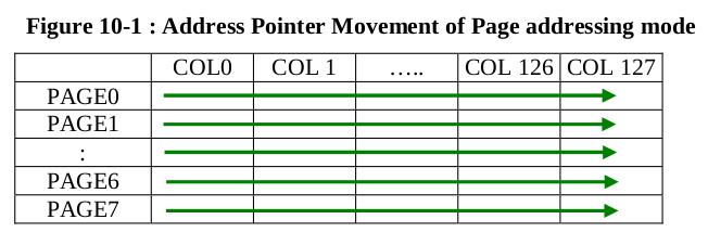
It is not only one pixel line… by looking closely, I could count the number of vertical pixels in this area: 8. 8, like a byte. On monochrome displays each pixel is a bit, and we are sending bytes, so accessing a single pixel line is impossible. We can only access a bunch of 8 lines, called a “page” in the datasheet. This display has 64 vertical bits, so 8 pages. And here what we see is page 0 being written and not the other ones!
Logic analyzer
After I soldered small cables to the SPI testpoints and slowed down my SPI bus speed for a better capture, I could spy on the bus.
I verified once again my startup command values, in hexadecimal magic numbers, so it is a good time to check if the Zephyr configuration is all right.
Then I moved on to data transfers.
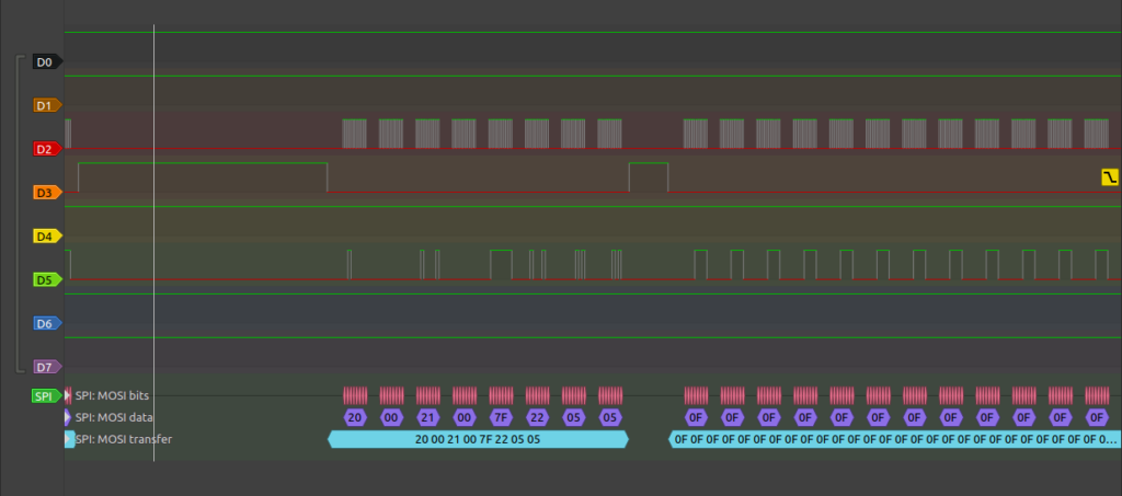
D/C line not shown because I tore the testpoint away…
The first batch is command, the 0x0F is data
Each data batch starts by the following command:
20 00 12 00 7F 22 05 0520h sets up the memory addressing mode. Mode 0x00 means that the pixel pointer auto-increments across columns, then across lines, so you just have to set start and stop coordinates and send all of your pixel in a rows. Different drivers can have different communication requirements, and sometimes you can only update line by line.
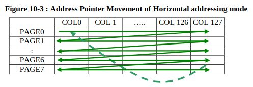
When I finally understood that the SSD1309 supports 3 different ways of batch sending data, I was getting the urge to try out another one. I thought I had to change the driver code but I was luckier that expected.
The SSD1306 driver happens to bring support for not only Solomon products, but also for something called Sinowealth SH1106. Let’s compare its datasheet with SSD1306’s.
Left: SH1106 datasheet, right: SSD1306 datasheet
In the SH1106 version, we only have support for “page addressing mode”, where data has to be sent line by line 8 lines by 8 lines. By default, the Zephyr driver uses the fancy auto-increment, but it has a specific “ssd1306_write_sh1106” if you set your compatible to sinowealth,sh1106.
So I tried with the sinowealth,sh1106 compatible, which uses the “page addressing mode”, and it worked.
I think my display actually ships with the Sinowealth chip, or another brand, not the Solomon. Maybe they are marked as equivalent references and it depends on production runs, maybe the datasheet is wrong or not updated, or maybe the manufacturer bought chips from a shady component broker who changed the labels to get more margin. Anyway, now I know that this module will not work with the auto-page increment!
Zephyr display subsystems and samples
Zephyr has 2 main display abstractions:
- CFB or Character Frame Buffer allows you to create text or simple graphics easily
- LVGL is a complete GUI API, including keys or touchscreen interactions.
Before trying out any of those:
- Run the samples/drivers/display code for your board
- Set up the Zephyr simulator to be able to compare expectations VS reality.
west build -b native_sim/native/64 -p always ./samples/driver/display
./build/zephyr/zephyr.exe --rt-ratio=10
The drivers/display should look like this on RGB 64×128:
samples/driver/display
And on monochrome 64×128:
CFB sample
Monochrome 64×128:
samples/subsys/display/cfb
Monochrome 360×240:
samples/subsys/display/cfb
LVGL sample
⚠ Don’t forget to disable the CFB module first. Both subsystems cannot coexist.
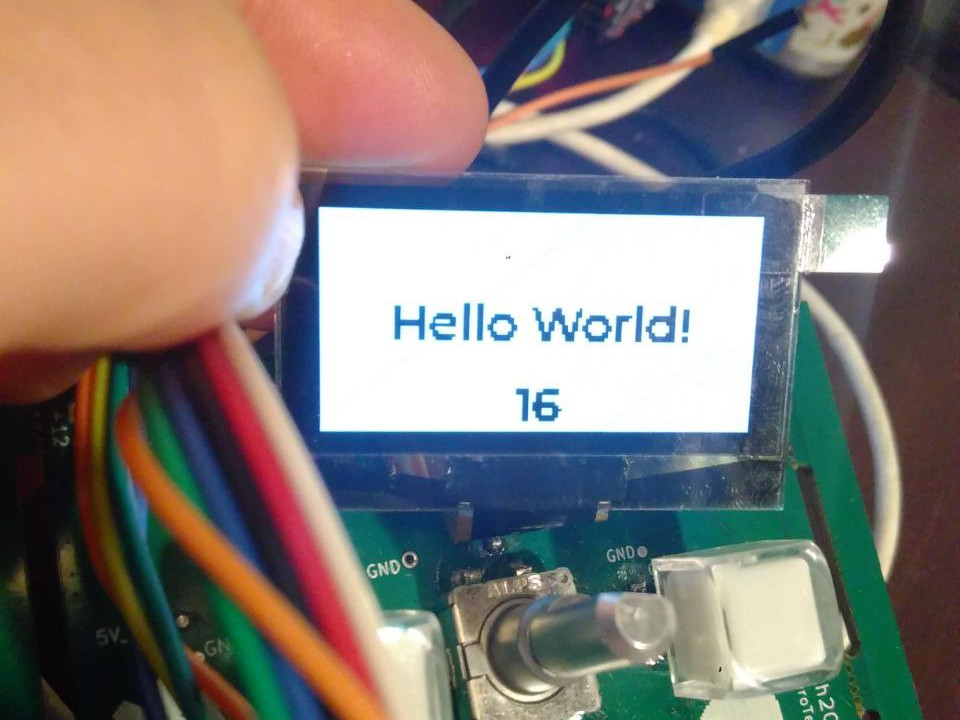
Here is the monochrome LVGL Hello World sample. If you add input subsystems, it will also display them and make them react to inputs.
samples/subsys/display/lvgl/
There is another LVGL sample, more optimized for big RGB displays, here in 360×240:
samples/modules/lvgl/
Conclusion
As a complete display newbie, buying my first display and making it work sure was an adventure. However, I did not have to write one single line of code, I could choose the display I really wanted, and it all worked out beautifully and in no time. I am convinced that Zephyr’s excellent support will change the experience we have with displays in embedded systems.
Project repository
There is a lot going on here, but the display support part is working: https://github.com/everedero/asynthosc_fw