


Analog to Digital Converters! Those versatile hardware blocks are typically used to retrieve data from analog sensors or board voltage rails.
All the information you need about the Zephyr ADC functions can be found on the ADC API documentation. Let’s have an overview of this API and create a new code sample.
Overview
In order to read an analog input, you will need:
- To initialize the ADC inputs, with correct hardware pinmux and options,
- To run a read function, like adc_read, adc_read_dt or adc_read_async.
A Zephyr ADC read function requires 2 inputs:
- An ADC hardware device, as device or as device tree spec,
- An object of type adc_sequence telling the function what to retrieve from said ADC device and how.
In order to create this adc_sequence object, two options:
- Automatically initiate it from device tree parameters with adc_sequence_init_dt. This function takes a device tree adc_dt_spec object as an input, and fills in the adc_sequence object channels, resolution and oversampling fields with the corresponding zephyr,parameter from the device tree channel description:
&adc0 {
    [...]
    channel@0 {
        reg = <0>;
        zephyr,gain = "ADC_GAIN_1";
        zephyr,reference = "ADC_REF_INTERNAL";
        zephyr,acquisition-time = <ADC_ACQ_TIME_DEFAULT>;
        zephyr,resolution = <12>;
        zephyr,oversampling = <0>;
    };
};
Device tree channel description
- Manually create and instantiate the adc_sequence object.
Recipe for an adc_sequence object
Multichannel ADC reading
In order to configure a sequence with several channels, it is necessary to initialize the sequence channels parameter manually.
The resolution and oversampling parameters will be applied to all channels.
All ADC channels have to belong to the same ADC hardware driver.
ADC channels are selected by the channels parameters in the adc_sequence object. This parameter is a bitmask.
For example, for and ADC with 3 channels 0, 3 and 5:
&adc0 {
      channel@0 {
            reg = <0>;
            [...]
      };
      channel@3 {
            reg = <3>;
            [...]
      };
      channel@5 {
            reg = <5>;
            [...]
      };
};
Device tree example channels description
Bitmask is 0b101001 = 0x29.
Number of samples
The number of samples to be read on each channel in a single read function call is selected by the extra_samplings parameter.
This parameters is: number of samples, minus one.
- By default, extra_samplings = 0, 1 sample is selected
- To select 8 samples: extra_samplings = 7
When several samples are selected, the function sleeps options.interval_us between each sample. This value cannot be optimally fast or precise because it is based on kernel system timer, around 10-50 kHz (20us-100us precision). For audio quality, it is necessary to bypass the kernel and configure a hardware timer.
It means no analog microphones capability yet…
ⓘ How to get the current systick
Menuconfig will give the systick and system clock information.
west build -t menuconfig- SYS_CLOCK_TICKS_PER_SEC(=10000) System tick frequency (in ticks/second)
- SYS_CLOCK_HW_CYCLES_PER_SEC (=216000000) System clock’s h/w timer frequency
ⓘ Oversampling is not available when several sample reads are enabled.
Buffer!
All this data needs a nice, big buffer to store it. This buffer is linked in the adc_sequence object, as a (void*).
It has to be a big enough buffer. To compute its size, multiply:
- Size of read data read (usually uint16_t, because most ADC are 12 or 16 bits)
- Number of samples per channel (1 + extra_samplings)
- Number of channels
For instance, a 12-bits ADC with 3 active channels and 6 simultaneous read will have to be 36 bytes wide, or 18 uint16_t.
ADC sequence configuration
Buffer with 6 uint16_t samples and 3 channels (0, 3 and 5) (unit = byte)
When the read function returns, the data will be available in the buffer.
Custom callback
adc_sequence.options has a callback field, empty by default. It allows to call an optional function every time a value is read.
Timing considerations
DMA use is selected by project options, and then, works by magic. ADC with DMA is not available on every hardware.
In my case, I have an STM32 target, DMA use is enabled in prj.conf.
CONFIG_DMA=y
CONFIG_ADC_STM32_DMA=y
prj.conf
In order to know what it does exactly, refer to the driver implementation in drivers/adc/adc_stm32.c.
DMA activation can be checked with devmem shell, or with debugger by stepping into the driver implementation.
Side note: debugging with devmem
Devmem proves very useful if you plan to customize or debug the ADC driver implementation itself: it allows to verify easily that the Zephyr driver has correctly set up the SoC register options.
The reference manual for our STM32 MCU tells us that our ADC1 uses DMA2, Channel 0, Stream 0.
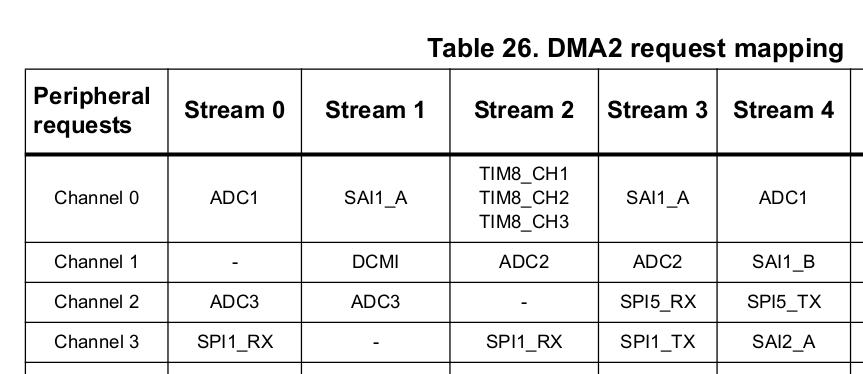
In the register boundary addresses table, I find my DMA2 registers start address: 0x40026400
In the DMA registers detail section, I find out that my stream is configured by the DMA_SxCR register, and channel selection is bits 27:25.
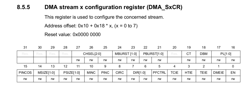
DMA_SxCR: Address offset: 0x10 + 0x18 * x, (x = 0 to 7)
DMA2_S0CR address is:
0x40026400 + 0x10 + 0x18*0 = 0x40026410
$ devmem 0x40026410
Read value 0x2c10
This value is not all zeros: I have some parameters here, such as the TCIE bit 4 set to 1, enabling the Transfer Complete interrupt. Bits 27:25 are set to 0b000: channel 0 is selected. DAC DMA looks correctly set up.
Keep in mind that this example depends on SoC and SoC architecture, you will have to dig into your favorite manufacturer’s documentation.
In this case, adc_read triggers one sequence. Processor is sleeping between reads, thanks to DMA automation. After reading a sequence, it returns.
With custom callbacks on top:
To make it infinite, configure a thread, and use adc_read_async.
And now, a code sample
https://github.com/everedero/zephyr/tree/sample_multi_adc, in file samples/drivers/adc/adc_multichannel/src/main.c
In this example, main reads 32 samples from 6 different channels in ADC1.
It features a custom callback called adc_callback printing the buffer each time a new sample is read, so every 32 readings.
It runs the sequence 3 times with a 100 msec sleep between each.
Conclusion
Sampling with DMA
Here is a zoom-in on the trace while retrieving 32 samples from 2 channels. Notice all this time spent in the idle thread while hardware is working hard:
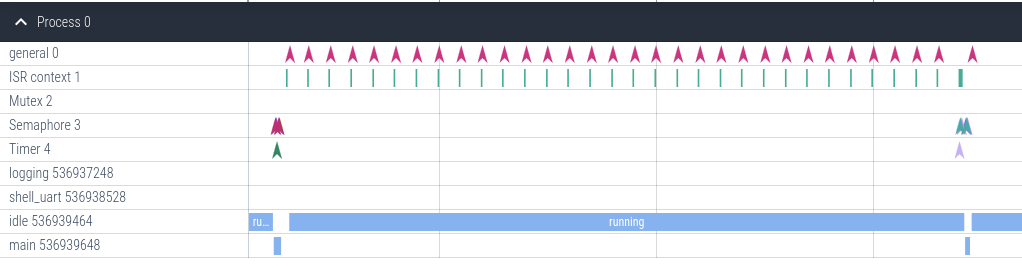
The ISR shown here is dma_stm32_irq_handler, in drivers/dma/dma_stm32.c.
ⓘ To know how this beautiful trace was made, refer to my tracing how-to: https://redero.fr/?p=649&lang=en
Spending time in idle thread
Zephyr version used here: V3.7.0