


In the music gear world, lots of small shops develop their guitar pedals or synthesizer modules. Amongst their numerous hurdles, they have to face the fact that custom mechanical parts are quite pricey. Front panel plates, typically in aluminium with holes and engraving, are no exceptions.

On the other hand, PCB manufacturing cost got really cheap, so an idea emerged: what if, instead of those aluminium or steel panels, we manufactured those… in PCB?
PCB allows:
- To have precise holes to mount connectors, buttons or switches,
- To write text with quite thin fonts (as silkscreen)
But it also allows for some additional creativity!
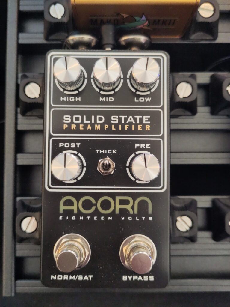
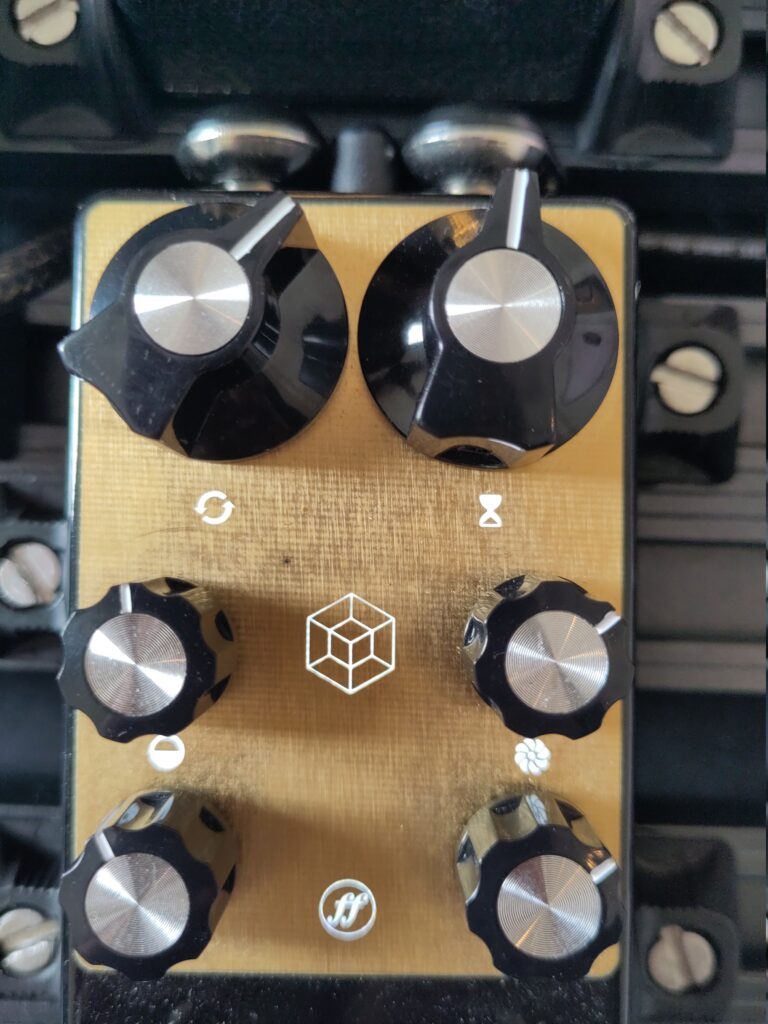
Gold is the color
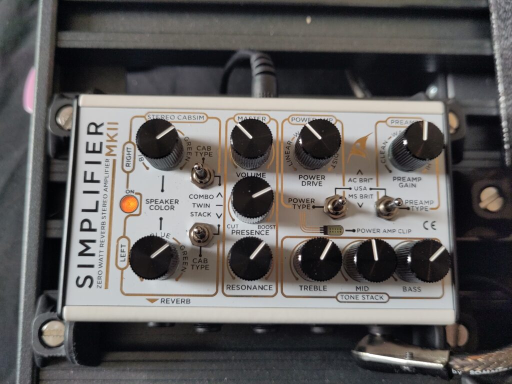
On this amplifier, the front panel is a white soldermask PCB, with black silkscreen. Switches and potentiometers are mounted as they usually are, we can assume a “real” PCB is mounted behind this “mechanical” PCB.
But what about gold? The third color is a soldermask opening, with gold finish option. It is a little bit more expensive than standard option, but very beautiful.
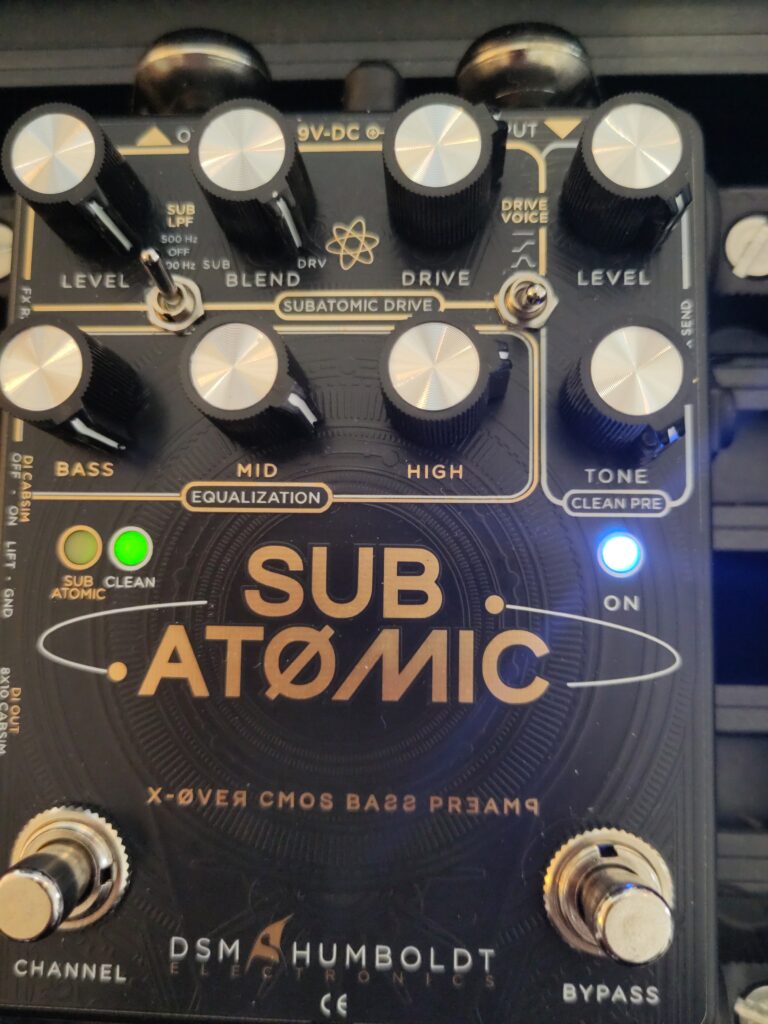
Soldering some components on it
Obviously, since it is a PCB, it allows soldering components on it.
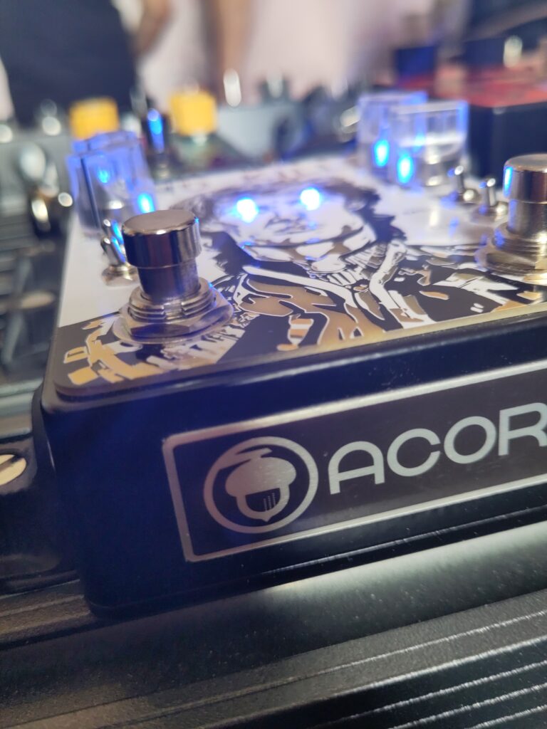
By the way how can you spot a PCB used as a decorative front plate? Looking at its edge, PCB is easy to spot.
Naked FR4
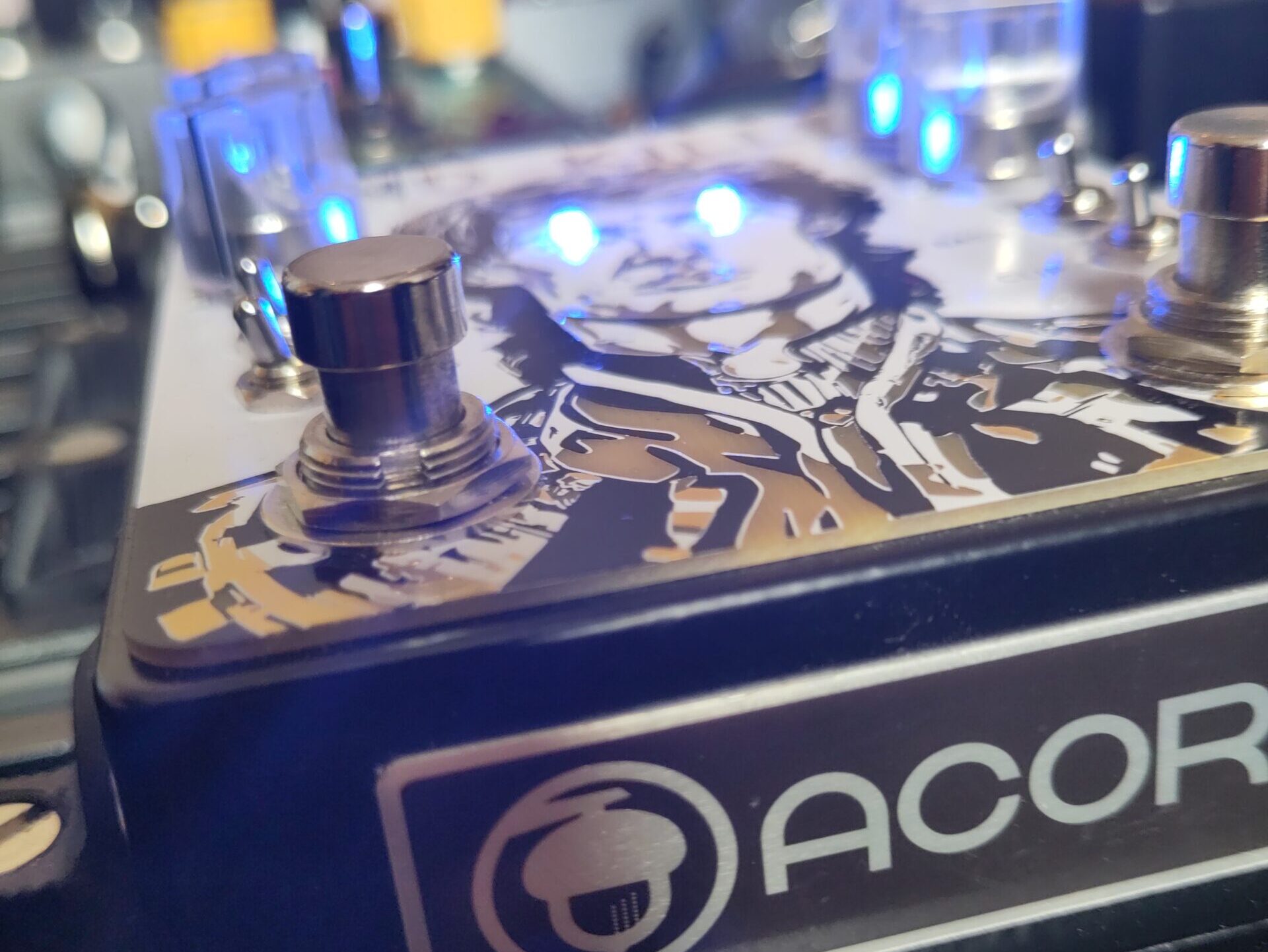
If copper, soldermask and silkscreen are removed on every layer, this awkward beige-green, half-translucent plastic color appears. But surprisingly, if you place LEDs behind, this plastic makes a quite okay light guide.
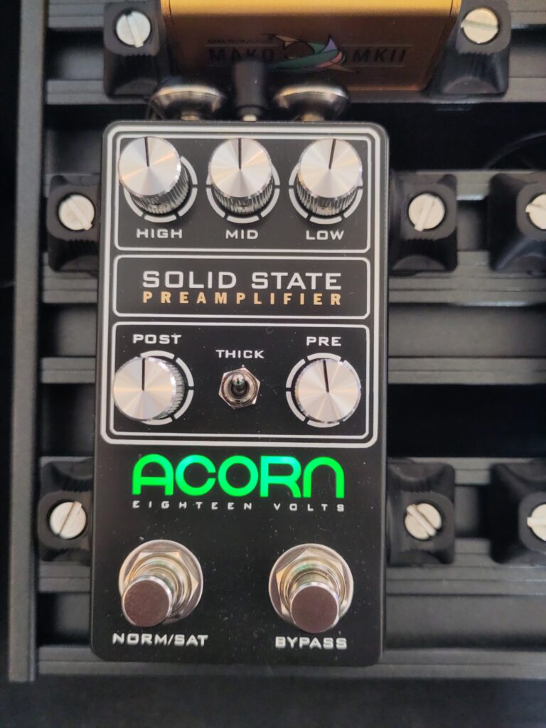
I could not guess if those LEDs are on the “real” PCB behind, or if they are reverse-mounted on the front-plate PCB. I bet for the first option, because otherwise, we would see the LED pads, since they have to be made of opaque copper.
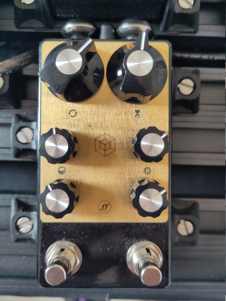
Carved in copper
The copper layer adds a small depth to the PCB, so that even with soldermask, we see the copper raised texture. So this brand chose to make a engraving-style decoration.
No more soldermask
We see a lot of black and white as soldermask colors. But this one brand decided to completely remove soldermask.
No-limit PCB Art
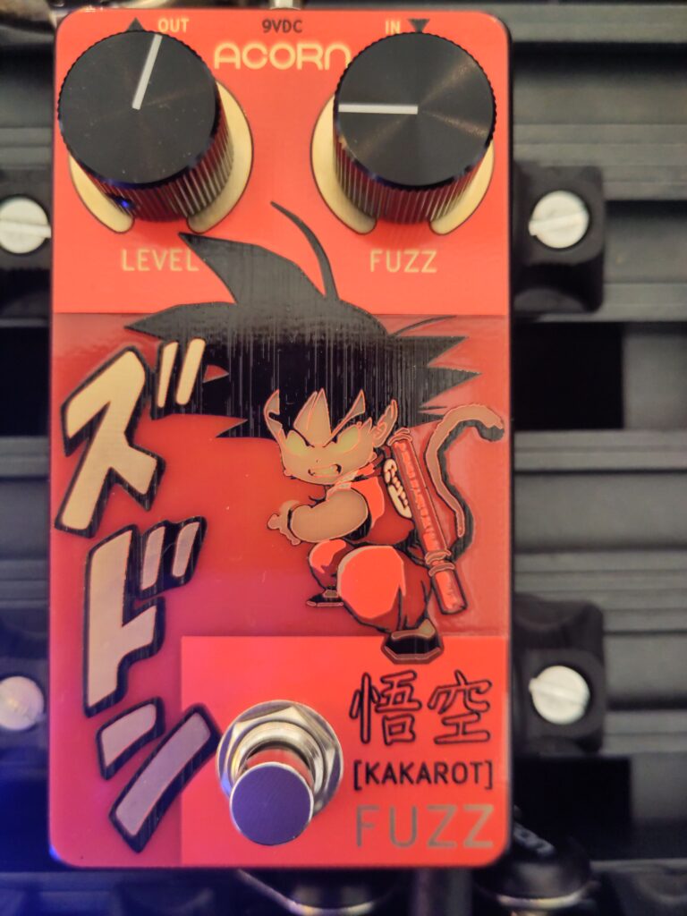
New creative idea: soldermask has a slightly different color if there is copper below or not. So here we have several colors:
- Naked FR4: translucent beige/green
- FR4 + soldermask: dark red
- FR4 + copper + soldermask: light red
- Silkscreen: black
- FR4 + Copper + ENIG: gold
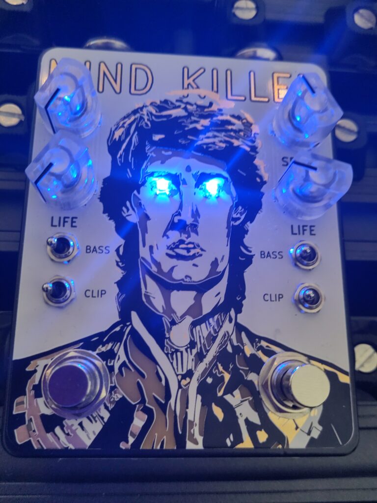
Very pretty. But wait until you see the LED version…
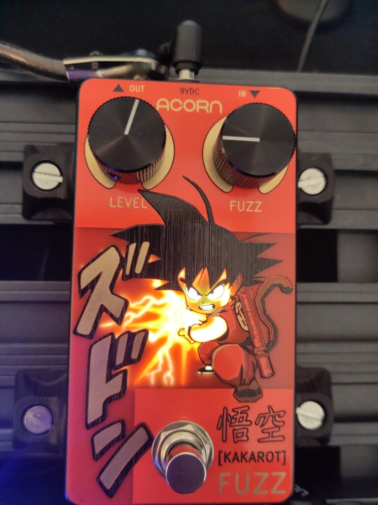
We can guess there is bottom copper to mask the LED. But I do not understand how they made 2 different light intensities…
Buttons!
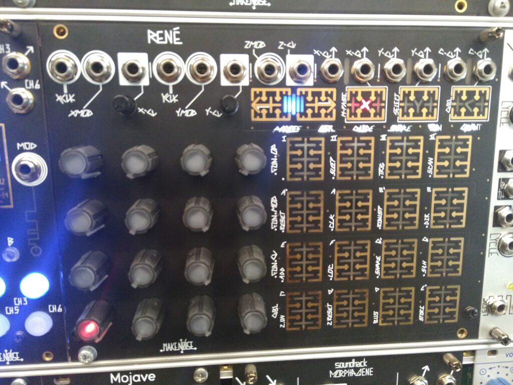
Backlight buttons made of PCB? What else could we ask for?
Here I am suspecting the tech used is capacitive sensing, even if it looks like some sort of resistive sensing between the two sides of soldermask opening. I played with it a little and I think I can trigger the button while only touching one half of the copper shape, so it felt capacitive.
100% PCB
It might be my ultimate engineering goal: a PCB being a product on its own, like the Pocket Operator series from Teenage Engineering. There is even a small PCB bit for product shelving: even the packaging is made from PCB.
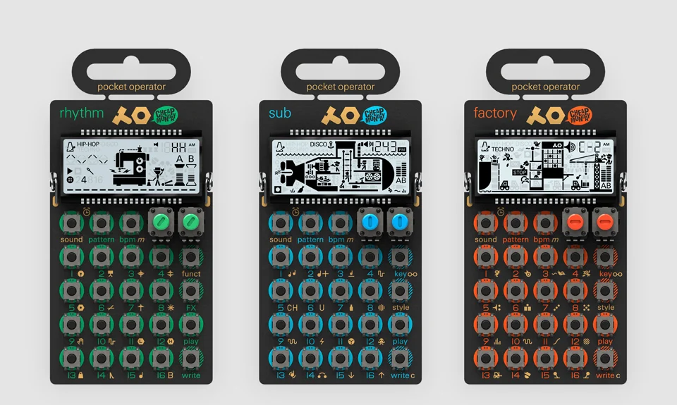
Teenage Engineering Pocket Operator
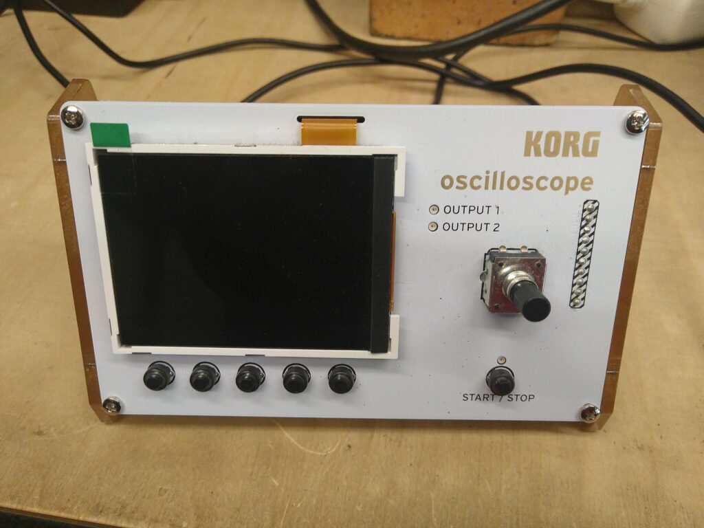
I also spotted this small kit oscilloscope from Korg. It is sold as an origami-style kit, on a multi-PCB panel with V-cuts, so you can cut and assemble it yourself.
Conclusion
So what are my takeaways from all of this?
Disclaimers
- I thought using PCB instead of aluminium would be bad for your carbon footprint, so I made a quick check. Surprisingly, it turns out that producing a non-equipped PCB has a carbon footprint that is very close to what an aluminium plate of similar dimensions would. This is probably due to the PCB containing lots of plastics and not that much copper.
- However, if you think about recycling, PCB is worse than an aluminium plate, because the latter can be fully recycled.
- Be careful while drawing stuff with copper: let those disconnected from your circuits to avoid antenna effects. Connector bodies, LED supplies, and every electrical contact you will make to your front panel plate, have to be kept separated from your art copper.
I want carbon footprint calculations!
Assuming we want an aluminium slab of 10 x 15 cm, 1,6mm thick.
- Aluminium density ≈ 2700 kg/m³
- CO₂ emissions (Europe) ≈ ~6.6 kg CO₂/kg Al
- CO₂ emissions (World average) ≈ ~14.6 kg CO₂/kg Al
So:
vol = 1.6e-3 * 10e-2 * 15e-2 = 2.4e-5
mass = 2700 * vol = 0.0648
emission = 0.43 kg (Europe) or 0.94 kg (World)
For an equivalent 10×15 cm PCB
- CO₂ emissions ≈ 60-70 kg / m2 PCB (source)
surface = 10e-2 * 15e-2 = 0.015
emission = 0.90 kg to 1.05 kg
Other ideas?
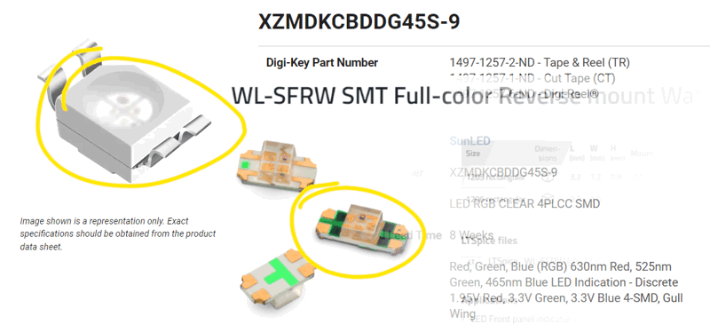
- From my observations, LEDs are either mounted on the main PCB, or on top of the panel PCB. I did not spot any reverse-mounted LEDs.
- Did anybody try playing with semi-flex? It is another type of FR4 abuse, it consists in carving grooves into the PCB in order to be able to fold it.
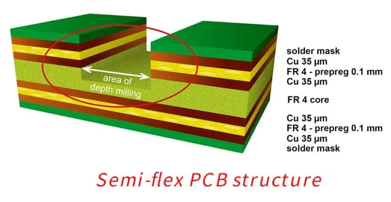
If you really want to go crazy, try semi-flex.
I hope this article will inspire and motivate you for your next awesome projects. Give me lots of content for my next articles!